User Manual – Rev BE AMETEK Programmable Power
MX Series 188
5. Principle of Operation
5.1 General
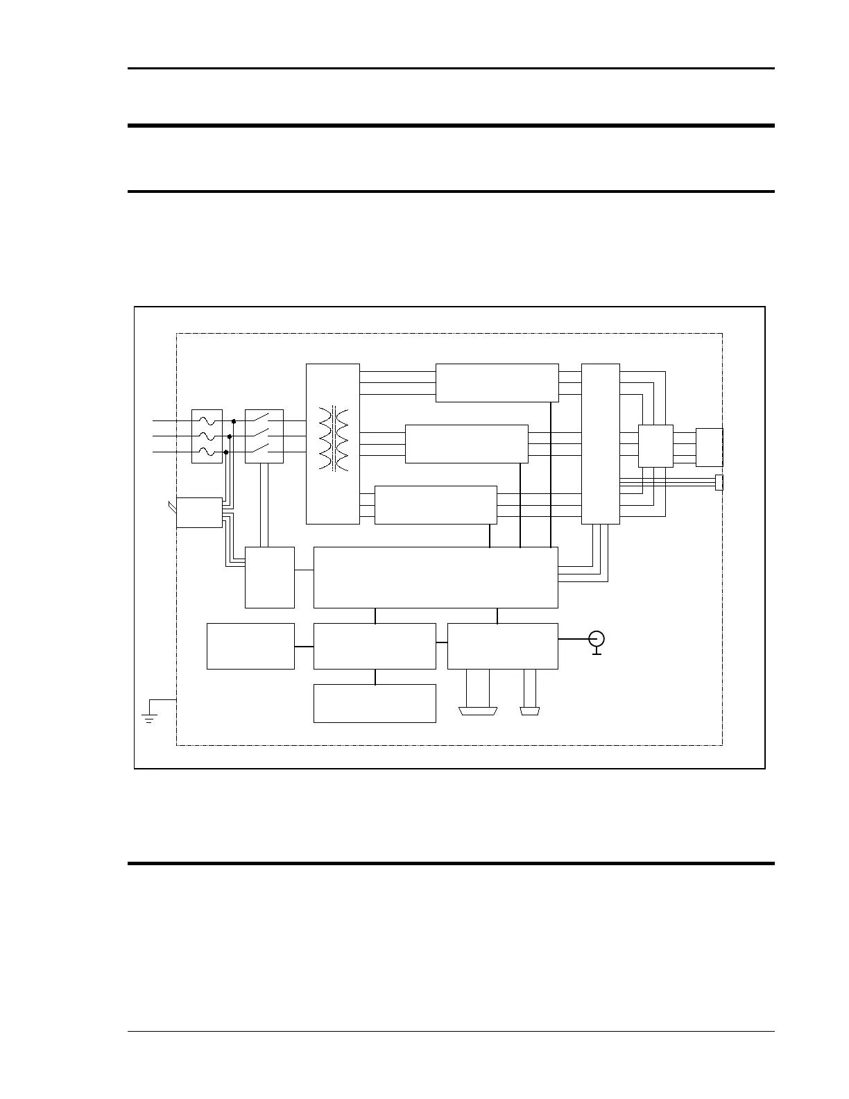
An explanation of the circuits in the MX Series is given in this section. Refer to
Figure 5-1 for a basic functional block diagram of the system. Figure 5-2 shows
a more detailed system interconnect for a MX-45-1 single-phase output unit.
Other models have slightly different output configurations.
Figure 5-1: MX Series Functional Block Diagram
5.2 Overall Description
Three-phase input power is routed from the back of the cabinet to a fuse holder
terminal block located in the bottom front of the unit. The lower front access
panel must be removed to gain access to the AC input connection fuse block.
From the fuse block, the AC input is connected to the three-phase input
transformer primary. The input transformer provides the required isolation
between input and output of the MX and accommodates various input voltage
POWER
MODULE A
POWER
MODULE B
POWER
MODULE C
Fuse
Block
Input
Transformer
AC
Input
Main
CB
System
Interface
Board
LV
Supply
Controller
CPU / Phase A
Controller
Phase B & C
Keyboard /
Display
Remote
Interface
IEEE-488 RS232C
K1/K2 Main
Contactor
& soft start
Current
Voltage
Sense
Board
Range
Mode
Select
Output
Terminals
Ext I/O
Ext.
Sense
AC 3ø
A
B
C
N
Gnd