User Manual – Rev BE AMETEK Programmable Power
MX Series 60
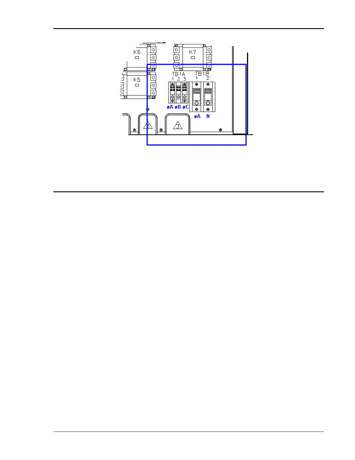
Figure 3-6: Location of Output Terminals (Front view)
3.6.3 MX22.5-1, MX45-1, MX30-1, MX22.5-3Pi, MX30-3Pi and MX45-3Pi 1 ø mode Output
Wiring Diagram
Figure 3-7 shows the required output connections for a MX30-1, MX45-1, MX30-
3Pi or MX45-3Pi in single-phase mode output configuration (rear-view
perspective). See section 3.6.4 for the MX30-3Pi or MX45-3Pi in three-phase
mode.
Always disconnect all input power from the MX before removing the front panel
cover that provides access to the input and output terminal connections. Route
the wires from the back of the MX to the front in the provided cable guides.