User Manual – Rev BE AMETEK Programmable Power
MX Series 80
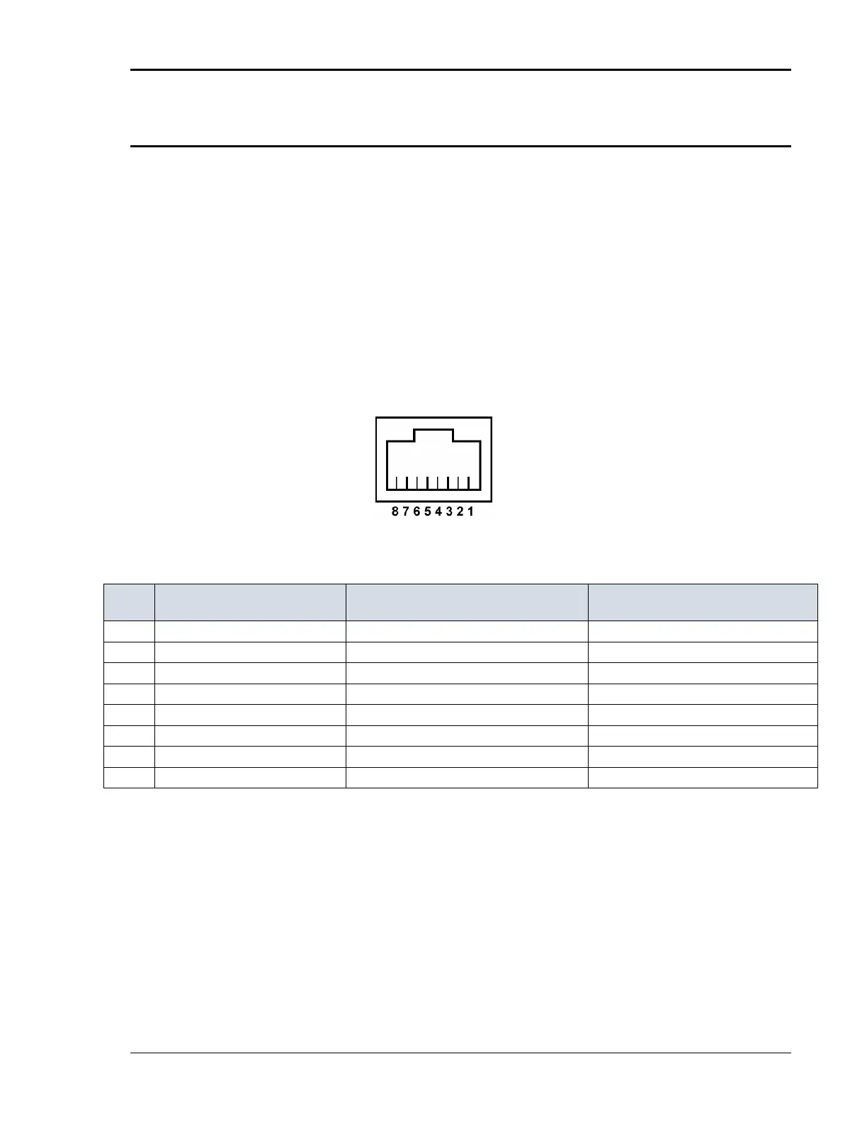
3.7.7 LAN Interface – RJ45
An optional RJ45 Ethernet 10BaseT connector is located on the rear panel for
remote-control. A standard RJ45 UTP patch cord between the AC Source and a
network Hub may be used to connect the AC source to a LAN. For direct
connection to a PC LAN card, a crossover RJ45 cable is required. Consult your
network administrator for directions on connecting the AC source to any
corporate LAN.
If the –LAN Ethernet interface option is present, the MAC Address (Media Access
Control) of the Ethernet port is printed on the serial tag of the power source.
The serial tag is located on the rear panel of the unit.
For information on how to set up a network connection or a direct PC connection
using the LAN interface, refer to the MX Series Programming Manual P/N 7003-
961 distributed in Adobe PDF format on CD ROM CIC496.
Ethernet TPE10BaseT /
100BastT / 1000BaseT
EI A/ TI A 5 68B
Crossover
1 Transmit/ Receive Data 0 +
White with green stripe White with orange stripe
2 Transmit/ Receive Data 0 -
Green with white stripe or solid green Orange with white stripe or solid orange
3 Transmit/ Receive Data 1 +
White with orange stripe White with green stripe
4 Transmit/ Receive Data 2 +
Blue with white stripe or solid blue Blue with white stripe or solid blue
5 Transmit/ Receive Data 2 -
White with blue stripe White with blue stripe
6 Transmit/ Receive Data 1 -
Orange with white stripe or solid orange Green with white stripe or solid
7 Transmit/ Receive Data 3 +
White with brown stripe or solid brown White with brown stripe or solid brown
8 Transmit/ Receive Data 3 -
Brown with white stripe or solid brown. Brown with white stripe or solid brown
Table 3-11: RJ45 LAN Connector Pin-out.
Figure 3-17: LAN Interface Connector