User Manual – Rev BE AMETEK Programmable Power
MX Series 224
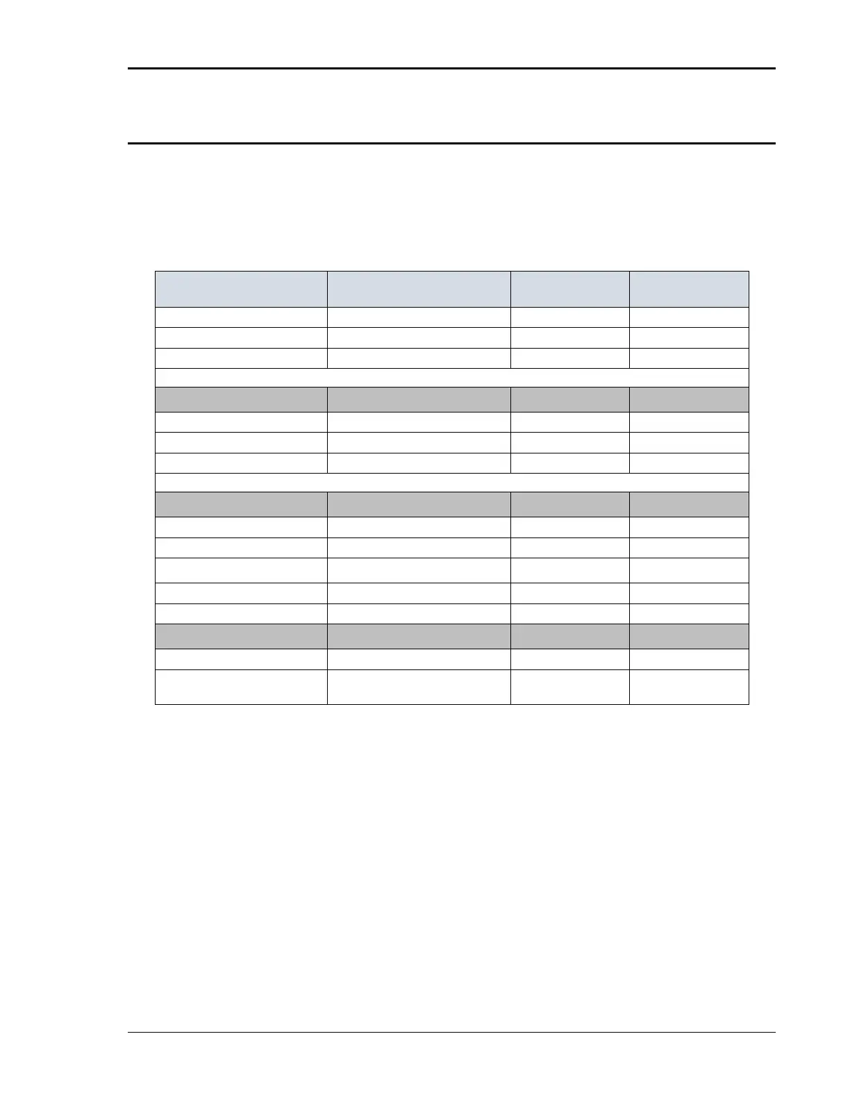
6.4.9 Output Calibration Summary
The following Table is a summary of the preceding calibration steps. Note that
Series II MX models have fewer calibration coefficients.
Program the following values in the table and make the adjustments in the
OUTPUT CALIBRATION screen. Select the phase to be calibrated by pressing
the PHASE key.
150 VAC range DC Zero 150 VAC range, 0.0 V VOLT ZERO 0 ± 15 mv DC
150 VAC range Volt FS 120.0 V, 60 Hz VOLT FS 120 ±0.05 VAC
150 VAC range Volt Hi Freq 120.0 V, 400 Hz V HI FR EQ 120 ± 0.05 VAC
Repeat the adjustments at 60 and 400 Hz until the output is within ± 0.05 volts
300 VAC range DC Zero 300 VAC range, 0.0 V, 60 Hz VOLT ZERO 0 ± 5 mV DC
300 VAC range Volt FS 240.0 V, 60 Hz VOLT FS 240 ± 0.05 VAC
300 VAC range Volt Hi Freq 240.0 V, 400 Hz VOLT HI FREQ 240 ± 0.05 VAC
Repeat the adjustments at 60 and 400 Hz until the output is within ± 0.05 volts
150 VDC range DC Zero 200 VDC range, 0.0 V VOLT ZERO 0 ± 5 mV DC
150 VDC range Volt +FS +160.0 V VOLT FS +160 ± 0.05 VDC
300 VDC range DC Zero 400 VDC range, 0.0 V VOLT ZERO 0 ± 5 mV DC
300 VDC range Volt +320.0 V VOLT F S +320 ± 0.05 VDC
Phase Offset B, C 150 VAC range, 120V, 60 Hz PHASE OFST ± 0.5°
Option -413
400 Hz
1800 Hz
R9, R10, R11
I NTER HAR M FS
20 ± 1.0 Vrms
20 ± 1.0 Vrms
Table 6-3: Output Calibration Table – MX Series I
 Loading...


