User Manual – Rev BE AMETEK Programmable Power
MX Series 168
4.5.2 3Pi Controller Measurements
For MX Series with the -3Pi controller, the following four measurement screens
are available:
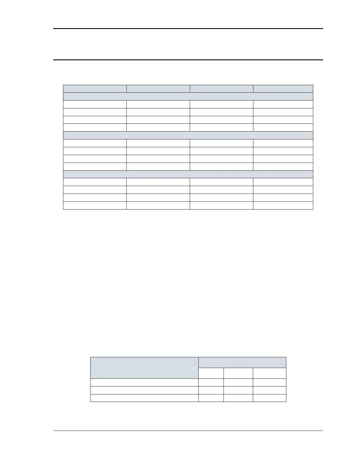
VOLTAGE AC r m s vo l t a g e DC Vo l t a g e AC r m s vo l t a g e
CURRENT AC rms current DC Cu r r e n t AC rms current
FREQUENCY Frequency n/a Frequency
P O WE R Real power n/ a n/a
VA P OWER Apparent power p o we r Apparent power
P EAK CURR Highest AC current found Highest DC current found Highest AC current found
P O WE R F AC T Power factor n/ a Power factor
CRES T FACT Cr e s t f a ct o r n/ a Cr e s t f a c t o r
VOLT THD Voltage distortion n/ a Voltage distortion
CURR THD Current distortion n/a Current distortion
I NS T P K CURR Instantaneous peak current Highest DC current found Instantaneous peak current
P HAS E Phase angle n/a Phase angle
The 3Pi controller has a fourth measurement screen for harmonics and trace
analysis measurements. This subject is covered in the next chapter.
NOTE: The V and I distortion calculations are based on H2 through H50 with the
RMS current in the denominator. Note that some definitions of THD use the
fundamental component (H1) as the denominator. This may result in different
readings between instruments depending on the implementation chosen.
Measurements are always running in the background. When the user selects a
measurement screen for display, the AC source first updates all the
measurement parameters before displaying the requested screen. This process
may take up to a second. Consequently, pressing the MEAS key may not always
bring up the selected screen immediately. There will be a perceptible delay. This
will prevent the screen from appearing with invalid or blank readouts.
The measurement method for voltage and current will depend on the power
source’s operating mode. The following table shows the return value type (rms
or average) and method of coupling when the measurement command is
initiated with a different extension at various operating modes (AC, DC, or AC +
DC).
Measurement Extension and Coupling
AC DC AC + DC
AC rms rms rms
DC rms rms average
Coupling AC DC DC