5-2
129390199 Operator Manual Component Identification
5.1 General Use this manual to become familiar with control locations and
functions before operating the sterilizer (refer to Figures 5-1 through
5-14). The controls for this sterilizer are contained within the control
touch screen. Control touch pads appear on the screen as needed
during each operation. Available controls change as the sterilizer
steps through different operations.
5.2 Sterilizer and
Cycle Controls
Refer to Figure 5-1.
• Steam Supply Valve – This is located behind the side access
panel (or within the wall enclosure), on the plumbing stand.
Ensure this is in the open position before trying to operate the
sterilizer.
• Water Supply Valve – This is located behind the side access
panel (or within the wall enclosure), on the plumbing stand. Refer
to Figure 5-1. Ensure this is in the open position before trying to
operate the sterilizer.
• Air Supply Valve – This is located behind the side access panel
(or within the wall enclosure), on the plumbing stand. Refer to
Figure 5-1. Ensure this is in the open position before trying to
operate the sterilizer.
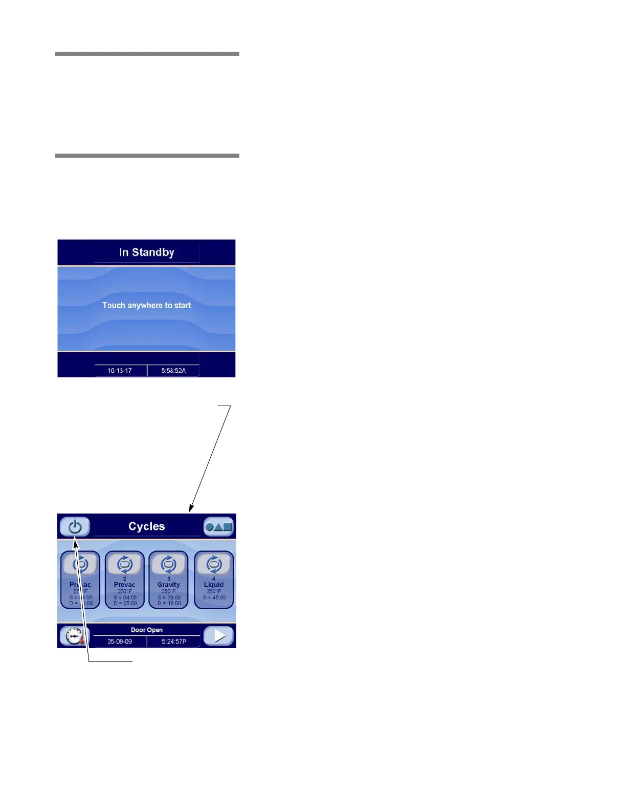
• Sterilizer Control Touch Screen – Control screens are visible
on the control touch screen. When powered up, the sterilizer is in
Standby mode.
Touch anywhere on the Standby screen to access the Cycles
Screen. From the Cycles Screen, touch the Standby button to
return the sterilizer to Standby mode.
NOTE: Touch-screen buttons responds to a light touch, pressure
or force is not required for operation.
• Emergency Stop Switch (with key) – Located on the front panel,
below the sterilizer control touch pad. Shuts off all outputs on the
sterilizer; the key is used to reset the switch following actuation.
This key is to be retained by the supervisor.
NOTE: Emergency Stop Switch not on Manual (Hinge) door
models.
• Sterilizer Key Switch (with key) – Located on the front panel
below the emergency stop switch. This switch sequentially
power up or power down the control system. Under normal
operating conditions this switch is left in the ON position at all
times.
• Door Open/Door Close Switches – These switches are used to
open and close power-operated doors. Switches not included on
Manual (Hinge) door models.
Touch Anywhere on Standby
Screen to Access Cycles Screen
(see below).
Touch Standby Button to
Return to Standby Mode
Cycles Screen
Standby Screen