Preliminary Technical Data UG-1828
Rev. PrB | Page 109 of 277
Besides that, another API “adi_adrv9001_Tx_Attenuation_Configure()” is provided to the user to set more configurations for
transmitter attenuation block, such as the transmitter attenuation step size.
Three transmitter attenuation modes are provided as defined by the enum “adi_adrv9001_TxAttenuationControlMode_e”:
typedef enum adi_adrv9001_TxAttenuationControlMode
{
ADI_ADRV9001_TX_ATTENUATION_CONTROL_MODE_BYPASS = 0,
ADI_ADRV9001_TX_ATTENUATION_CONTROL_MODE_SPI = 1,
ADI_ADRV9001_TX_ATTENUATION_CONTROL_MODE_PIN = 3,
} adi_adrv9001_TxAttenuationControlMode_e
BYPASS MODE
Bypass mode is selected when the transmitter attenuation mode is set as
“ADI_ADRV9001_TX_ATTENUATION_CONTROL_MODE_BYPASS”. In this mode, the transmitter attenuation functionality is not
used, which means 0dB total transmitter attenuation.
SPI MODE
SPI mode is selected when the transmitter attenuation mode is set as
“ADI_ADRV9001_TX_ATTENUATION_CONTROL_MODE_SPI”. In this mode, the user could set the transmitter attenuation value
via the API command “adi_adrv9001_Tx_Attenuation_Set()”.
SPI mode consists of two options, the TDD ramp mode and the constant-step size mode. The TDD ramp mode was designed for power
ramping in TDD systems. Note it is not supported in the current release. The constant-step size mode allows to control an exact constant
gain step size to reach the targeted attenuation level.
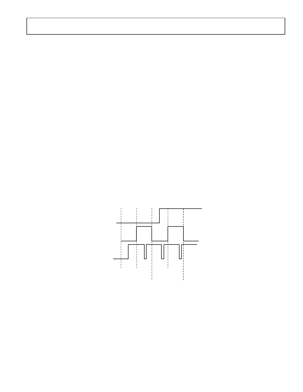
TDD Ramp Mode
The TDD ramp mode was designed for use in TDD systems. The user could program an “On power” and “Off power” for the next time
slot. The ramp rate can be controlled via a step size (tdd_ramp_step_size) and wait duration (tdd_ramp_wait_duration) between steps.
The ramp up or down could be initiated through API commands. Note those user interactions are currently not supported, but will be
provided in the future. A typical TDD ramp is depicted in Figure 116.
TDD_RAMP_STEP_SIZE
TDD SLOT
DESIRED Tx
ATTENUATION
IN RAMP UP
DESIRED Tx
ATTENUATION
IN RAMP DOWN
Tx ON POWER
FULL-SCALE OUTPUT POWER
Tx OUTPUT POWER
Tx OFF POWER
TDD_RAMP_WAIT_DURATION
ATTEN_RAMP_UP
ATTEN_RAMP_DOWN
24159-089
Figure 116. TDD Ramp Profile
Constant-Step Size Mode
In constant-step size mode, the transmitter attenuation controller ramps to the new transmitter attenuation value immediately after it is
set through API command. Again the slope can be controlled via a step size (const_step_mode_step_size) and wait duration
(const_step_mode_wait_duration) between steps. A typical output power transient for this mode is shown in Figure 117.
 Loading...