5 Serial Ports
5 – 14
Framing modes for receiving and transmitting data are independent. If the
receive frame sync width (RFSW) bit or transmit frame sync width (TFSW)
bit in the SPORT control register is a 0, normal framing is enabled. If the
RFSW or TFSW bit is a 1, alternate framing is used. The RFSW bit is bit 12
in the SPORT control register (0x3FF6 for SPORT0 and 0x3FF2 for
SPORT1), and the TFSW bit is bit 10. These bits are both cleared at reset,
so that normal framing in both directions is enabled.
For examples of normal and alternate framing, see “Configuration
Examples” later in this chapter.
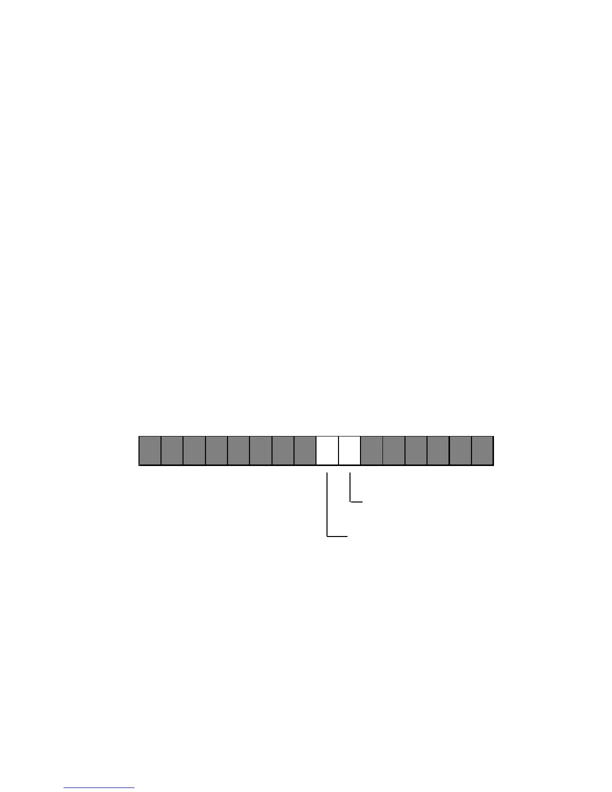
5.7.4 Active High Or Active Low
Framing sync signals for receiving and transmitting data can be either
active high or active low and are configured independently. If the invert
RFS (INVRFS) bit or invert TFS (INVTFS) bit in the SPORT control register
is a 0, the corresponding frame sync signal is active high. If the INVRFS or
INVTFS bit is a 1, the frame sync signal is active low. These controls apply
SPORT0 Control Register: 0x3FF6
SPORT1 Control Register: 0x3FF2
15 14 13 12 11 10 9 8 7 6 5 4 3 2 1 0
INVTFS (Invert Transmit
Framing Signal)
INVRFS (Invert Receive
Framing Signal)
INVRFS 0=Active High RFS
1=Active Low RFS
INVTFS 0=Active High TFS
1=Active Low TFS
Figure 5.8 INVTFS And INVRFS Bits In SPORT Control Register

 Loading...

