10 Memory Interface
10 – 16
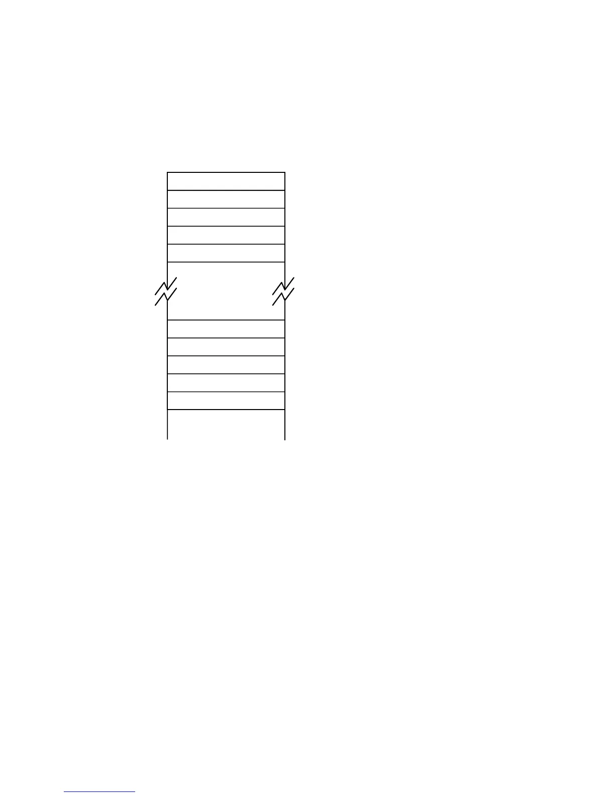
Word 0: USB
Word 0: MSB
Word 0: LSB
Page Length
Word 1: USB
Not Used
Word 7: USB
Word 7: MSB
Word 7: LSB
Not Used
Address
0000
0002
0003
0001
0004
001B
001C
001D
001E
001F
Figure 10.16 EPROM Contents
10.4.2 Powerup Boot & Software Reboot
Upon a hardware or software reset, the boot sequence occurs if the MMAP
pin is a logical 0. The boot sequence on reset always loads boot page 0.
After reset, boot loading can occur under program control from any one of
up to 8 different boot pages. The boot page select field (BPAGE) in the
memory-mapped System Control Register (see Figure 10.17) specifies
which boot page is to be loaded. To boot from a specific boot page, set
BPAGE to the desired page number and, in the same memory-mapped
register, set the boot force bit (BFORCE). When the boot force bit is set, the
software-forced booting sequence starts. Except for the page selection and
(possibly) the number of wait states, there is no difference between a
software-forced boot sequence and a reset boot sequence.
Tables 9.2–9.7 in the System Interface chapter show the state of the
processor control registers after a reset and after a software reboot.
Essentially, the processor’s control state is saved, but stacks are cleared
and execution starts at the restart vector, at program memory location
0x0000.

 Loading...

