4Data Transfer
4 – 9
4.4 PMD-DMD BUS EXCHANGE
The PMD-DMD bus exchange unit couples the program memory data bus
and the data memory data bus, allowing them to transfer data between
them in both directions. Since the program memory data (PMD) bus is 24
bits wide, while the data memory data (DMD) bus is 16 bits wide, only the
upper 16 bits of PMD can be directly transferred. An internal register (PX)
is loaded with (or supplies) the additional 8 bits. This register can be
directly loaded or read when the full 24 bits are required.
Note that when reading data from program memory and data memory
simultaneously, there is a dedicated path from the upper 16 bits of the
PMD bus to the Y registers of the computational units. This read-only path
does not use the bus exchange circuit; it is the path shown on the
individual computational unit block diagrams.
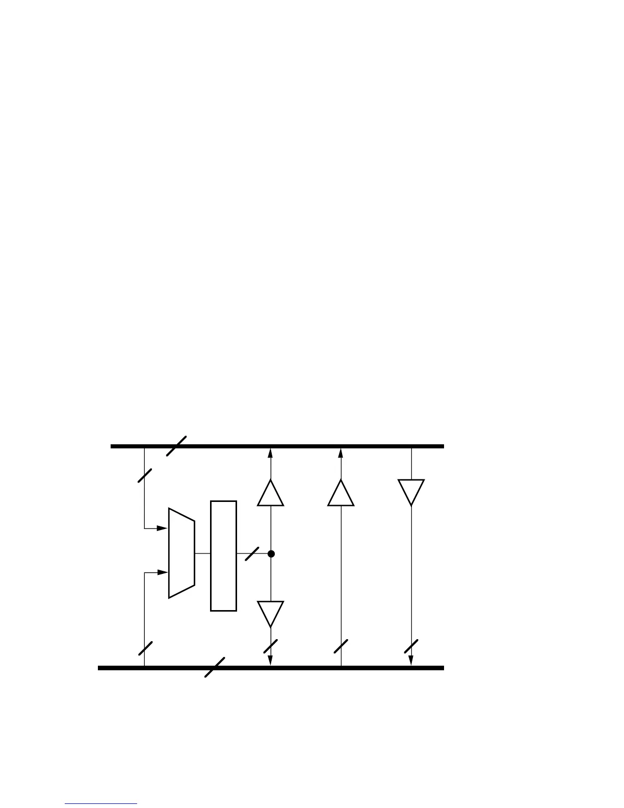
4.4.1 PMD-DMD Block Diagram Discussion
Figure 4.2 shows a block diagram of the PMD-DMD bus exchange. There
are two types of connections provided by this circuitry.
PMD BUS
DMD BUS
8 (LOWER) 16 (UPPER) 16 (UPPER)
24
16
16
M
U
X
PX
R
E
G
I
S
T
E
R
8
8
8 (LOWER)
16
8 (LOWER)
Figure 4.2 PMD–DMD Bus Exchange

 Loading...

