7 Host Interface Port
7 – 6
0x3FE60000000000000000
0123456789101112131415
21xx HDR0 Write
21xx HDR1 Write
21xx HDR2 Write
21xx HDR3 Write
21xx HDR4 Write
21xx HDR5 Write
Host HDR0 Write
Host HDR1 Write
Host HDR2 Write
Host HDR3 Write
Host HDR4 Write
Host HDR5 Write
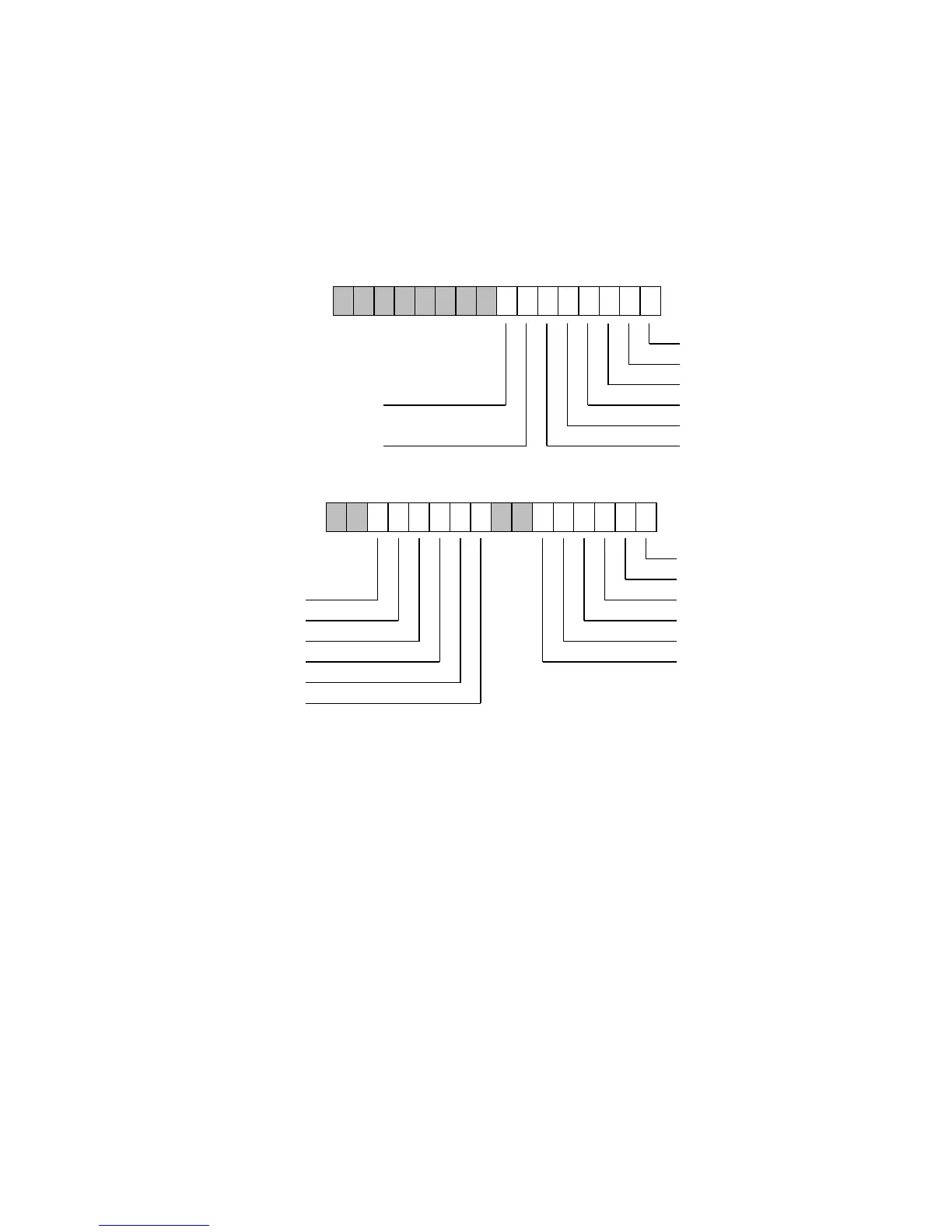
Figure 7.2 HIP Status Registers
The lower six bits of HSR7 are copied from the upper byte of HSR6 so that
8-bit hosts can read both sets of status. Bits 7 and 6 of HSR7 control the
overwrite mode and software reset, respectively; these functions are
described later in this chapter. The upper byte of HSR7 is reserved. All
reserved bits and the software reset bit read as zeros. The overwrite bit is
the only bit in the HSRs that can be both written and read. At reset, all
HSR bits are zeros except for the overwrite bit, which is a one.
7.4 HIP OPERATION
The ADSP-21xx core can place a data value into one of the HDRs for
retrieval by the host computer. Similarly, the host computer can place a
data value into one of the HDRs for retrieval by the ADSP-21xx. To the
host computer, the HDRs function as a section of memory. To the
ADSP-21xx, the HDRs are memory-mapped registers, part of the internal
data memory space.
0123456789101112131415
0x3FE7
21xx HDR0 Write
0000000100000000
21xx HDR1 Write
21xx HDR2 Write
21xx HDR3 Write
21xx HDR4 Write
21xx HDR5 Write
HSR7
HSR6

 Loading...

