7Host Interface Port
7 –
5
DMD BUS
16
HD15-0
Host
Control
Interface
HMD0
HMD1
BMODE
Read/write control
HSR6
HDR5
HDR4
HDR3
HDR2
HDR1
HDR0
HSEL
HACK
HRD/HRW
2
HWR/HDS
HSIZE
HA1-0
HIP
INTERRUPTS
2
SOFT RESET
Boot
Control
Overwrite Bit
HMASK
HA2/ALE
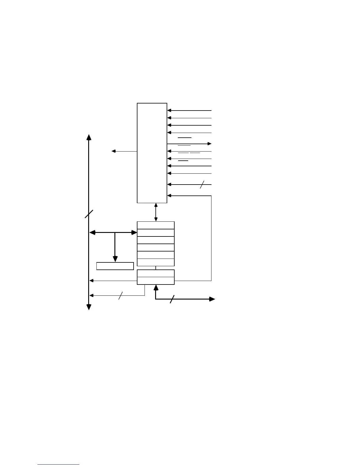
Figure 7.1 HIP Block Diagram
The HSR registers are shown in Figure 7.2, which can be found on the
following page. Status information in HSR6 and HSR7 shows which HDRs
have been written. The lower byte of HSR6 shows which HDRs have been
written by the host computer. The upper byte of the HSR6 shows which
HDRs have been written by the ADSP-21xx. When an HDR register is
read, the corresponding HSR bit is cleared.

 Loading...

