15
15 – 89
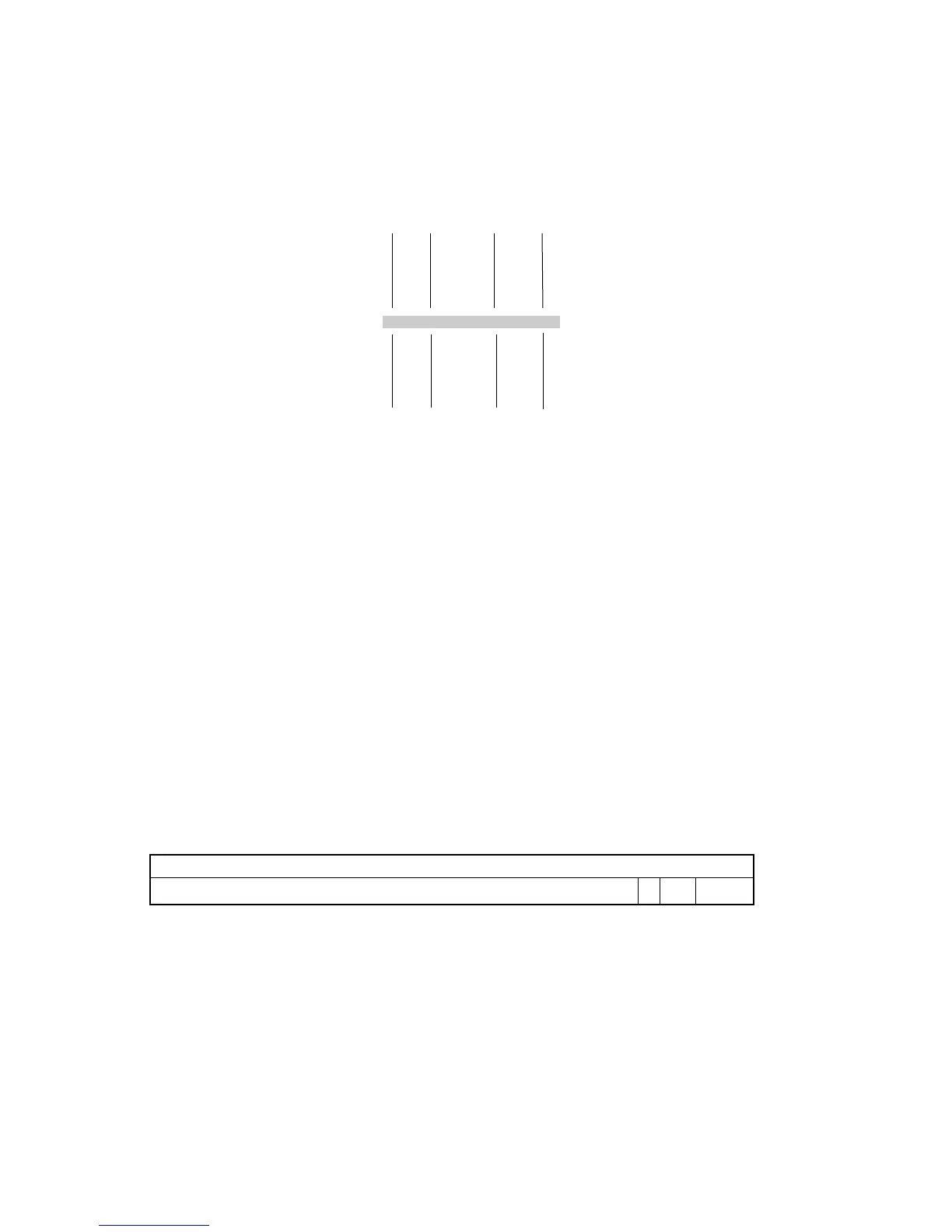
Syntax: MODIFY ( I0 , M0 ) ;
I1 M1
I2 M2
I3 M3
I4 M4
I5 M5
I6 M6
I7 M7
Example: MODIFY (I1, M1);
Description: Add the selected M register (M
n
) to the selected I register
(I
m
), then process the modified address through the modulus logic with
buffer length as determined by the L register corresponding to the
selected I register (L
m
), and store the resulting address pointer calculation
in the selected I register. The I register is modified as if an indexed
memory address were taking place, but no actual memory data transfer
occurs. For linear (i.e. non-circular) indirect addressing, the L register
corresponding to the I register used must be set to zero.
The selection of the I and M registers is constrained to registers within the
same Data Address Generator: selection of I0-I3 in Data Address
Generator #1 constrains selection of the M registers to M0-M3. Similarly,
selection of I4-I7 constrains the M registers to M4-M7.
Status Generated: None affected.
Instruction Format:
Modify Address Register, Instruction Type 21:
23 22 21 20 19 18 17 16 15 14 13 12 11 10 9 8 7 6 5 4 3 2 1 0
0 0 0 0 1 0 0 1 0 0 0 0 0 0 0 0 0 0 0 G I M
G specifies which Data Address Generator is selected. The I and M
registers specified must be from the same DAG, separated by the gray bar
above. I specifies the I register (depends on which DAG is selected by the
G bit). M specifies the M register (depends on which DAG is selected by
the G bit).
MISC
MODIFY ADDRESS REGISTER

 Loading...

