Section 4 Operation
4-60
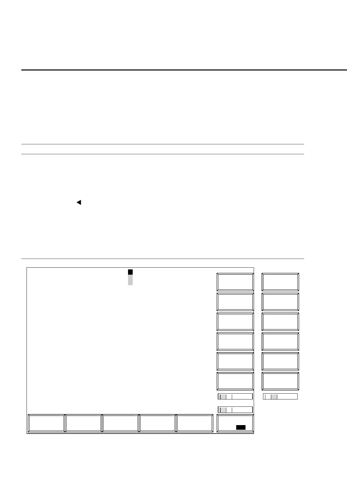
(2) Modulation analysis: Modulation Analysis screen
Use the parameters set on the Setup Common Parameter screen (see paragraph
4.3.5) and Setup TX Measure Parameter screen (see paragraph 4.3.6, (1)) to
analyze a modulated signal from the transmitter, and display a measured value
or waveform. (The TX power indicates the output power in the burst.)
• Display the Modulation Analysis screen according to the following steps:
Step Key operation Description
1. [Main Func on off] F6 Sets the Main Func on to display the Main Menu at the bottom of the screen.
2. [TX&RX Tester] F1 Sets TX&RX Tester mode.
The Setup Common Parameter screen appears.
3. [TX Measure] F1 Displays the first page of the TX Measure menu.
4. Next Menu [ ] Displays the second page of the Main Func menu.
5. [Start] F5 Sets Call Processing state to Idle.
6. Connect call. Turn on the power of the mobile station under test.
Wait until the Call Processing state becomes Idle (Regist) after Registration.
7. [NW Originate] F2 Sets Call Processing state to Loop Back.
8. [Modulation Analysis] F8 Displays the Modulation Analysis screen.
1
1 2
2
Mod. Anal.
MT8801 99/12/31 12:00:00 Measure : Continuous
<< Modulation Analysis (CDMA) >> Storage : Normal
Frequency
Carrier Frequency : 1900.000 001 0 MHz
Carrier Frequency Error : 0.001 0 kHz
Waveform Quality
ρ(Waveform Quality Factor) : 0.99947
τ(Timing Error) : 0.54 us
Modulation
RMS Vector Error : 1.35 % (rms)
Peak Vector Error : 8.22 %
Phase Error : 1.22 deg. (rms)
Magnitude Error : 0.58 % (rms)
Origin Offset : -45.00 dB
RF Power
TX Power : 6.52 dBm
Channel: 0000CH Frequency: 1000.000 000MHz Level:-10dBm
BS Output
Level
Sync
Channel
Level
Paging
Channel
Level
Traffic
Channel
Level
Main Func
On Off
#
###
Storage
Mode
Adjust
Range
Back
Screen
*
*
M
C
U
Calibration
->
Pilot
Channel
Level
#
Mod. Anal.
BS Output
Level Cal.
Back
Screen
->
1 2
Fig. 4-6 Modulation Analysis Screen
 Loading...


