Section 4 Operation
4-138
4.3.11 Closed Loop Power Control function
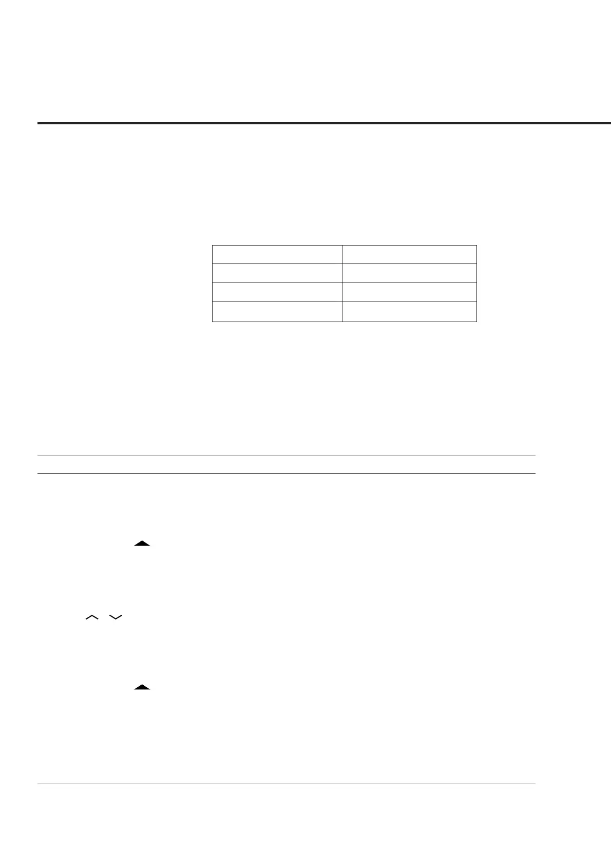
When the following conditions in the table below are satisfied on each the Setup
screen, FER screen, Power Meter screen (with IF Level Meter) and Modulation
Analysis screen; the Closed Loop Power Control function mode can be obtained. This
function controls the Tx power of the mobile station to the desired level using the
Closed Loop Power Control Bit.
Item Selection/Condition
Power Control Bit Pattern Closed Loop (Initial value)
(Reference Level) Auto Set On (Initial value)
Call Processing Loop Back or Conversation
(1) Setting parameter: Each Setup screen, Power Meter screen, Modu-
lation Analysis screen
The parameters of the Closed Loop Power Control function can be set, as de-
scribed below.
In this description, note that the steps 1 to 7 are not required in Preset Power On
mode.
Step Key operation Description
1. [Main Func on off] F6 Sets the Main Func on to display the Main Menu at the bottom of the screen.
2. [TX&RX Tester] F1 Sets TX&RX Tester mode to display the Setup Common Parameter screen.
3. [TX Measure] F1 The first page of the TX Measure menu appears.
4. Next Menu [ ] The second page of the TX Measure menu appears.
5. [Setup TX Parameter] F9 The Setup TX Measure Parameter screen appears.
6. [Power Control Bit Pattern] Move the cursor to this item.
[Closed Loop] Cursor Selects the Closed Loop, and set.
[ ] [ ] Set ((Reference level) Auto Set becomes ON, automatically.)
(* This can be also set on the Power Meter screen and Modulation Analysis
screen.)
7. [Back Screen] F12 The Setup Common Parameter screen appears.
8. Next Menu [ ] The second page of the Main Func menu appears.
9. [Start] F5 The Call Processing state becomes the Idle state.
10. Connect the call. Turn on the power of the mobile station.
Wait until the Call Processing state becomes the Idle (Regist) state after
Registration.
11. [NW Originate] F2 The Call Processing state becomes the Loop Back state.