Manual, Robotic Tool Changer, QC-210
Document #9620-20-B-210 Series Base Tool Changer-26
Pinnacle Park • 1031 Goodworth Drive • Apex, NC 27539 • Tel: 919.772.0115 • Fax: 919.772.8259 • www.ati-ia.com • Email: info@ati-ia.com
B-27
13. Secure the sensor assembly using the (2) M3 socket at head screws. Tighten to
12 in-lbs (1.4 Nm) using a 2 mm Allen wrench.
14. Install the (2) cable retaining tabs on Flat D of the Tool Changer body and secure
with the (2) M3 socket at head cap screws. Tighten to 12 in-lbs (1.4 Nm) using a
2 mm Allen wrench.
15. If the optional modules were installed on Flat D, install the modules.
16. Apply Loctite 242 to the M6 socket head cap screws. Install the (2) M6 Socket
Head Cap Screws that secure the module to the Tool Changer body and tighten to
70 in-lbs (7.9 Nm) using a 5 mm Allen wrench.
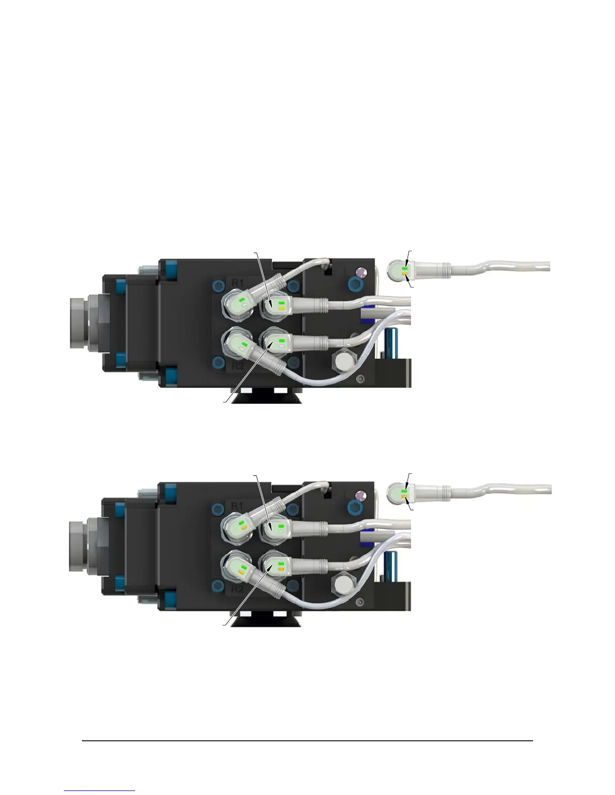
17. Conrm the operation of the Unlock sensor by unlocking the Tool Changer and
then checking to see If the Unlock sensor cable LED is on.
Figure 5.4—Unlock Sensor Cable LEDs
Unlock (U)
Lock (L)
Green LED (Power)
Yellow LED
(Switch Made)
18. Conrm the operation of the Lock sensor by locking the Tool Changer and then
checking to see If the Lock sensor cable LED is on.
Figure 5.5—Lock Sensor Cable LEDs
Lock (L)
Yellow LED
(Switch Made)
19. After maintenance is complete, return all circuits to normal operation (e.g.
electrical, air, water, etc.).
20. After the procedure is complete, resume normal operation.