Manual, Robotic Tool Changer, QC-210
Document #9620-20-B-210 Series Base Tool Changer-26
Pinnacle Park • 1031 Goodworth Drive • Apex, NC 27539 • Tel: 919.772.0115 • Fax: 919.772.8259 • www.ati-ia.com • Email: info@ati-ia.com
B-28
5.2.1.4 Lock and Unlock Sensor Assembly Replacement (with Sensor
Assemblies)
Parts required: Refer to Section 6—Serviceable Parts
Tools required: 2 mm, 2.5 mm, and 5 mm Allen wrench (hex key), torque wrench
Supplies required: Loctite 222 and 242
1. Place the Tool in a secure location.
2. Uncouple the Master and Tool plates.
3. Turn off and de-energize all energized circuits (e.g. electrical, air, water, etc.).
4. If there is an optional module on Flat B, C, or D, remove the (2) M6 socket head
cap screws that secure the module(s) to the Tool Changer body using a 5 mm Allen
wrench. Refer to Figure 5.6
Note: If the lock sensor is being replaced the module on Flat B may need to be
removed. If the module block access to the lock sensor it will need to be removed.
5. If equipped, lift off the optional modules from Flats B, C, and D.
6. Using a 2 mm Allen wrench, remove the (2) M3 socket at head cap screws and
the (2) cable retaining tabs on Flat D of the Tool Changer body.
7. For the lock sensor, remove the (2) M3 socket at head cap screws and the (2)
cable retaining tabs on Flat C of the Tool Changer body using a 2 mm Allen
wrench.
8. Unscrew the lock and/or unlock sensor cable connector from the air/valve adapter
or control/signal module.
9. Using a 2.5 mm Allen wrench, remove the (2) M3 socket head cap screws that
secure the lock and/or unlock sensor assembly to the Tool Changer body. Pull the
sensor assembly straight out from the Tool Changer body.
10. Remove the lock and/or unlock sensor assembly from the cable channels of the
Tool Changer body. Discard the removed sensor assembly.
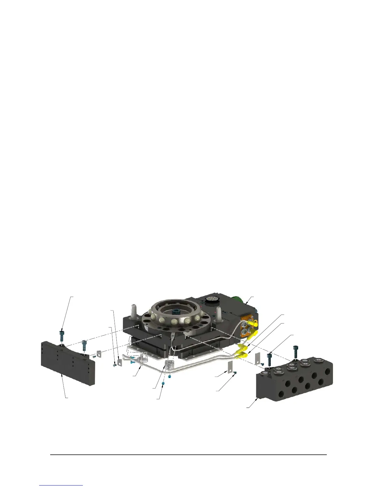
Figure 5.6—Lock and Unlock Sensor Assembly Replacement
Valve Adapter and
Control Module on Flat A
Remove Module
on Flat C
M6 Socket Head Cap Screws
M6 Socket Head
Cap Screw
M3 Socket Head
Cap Screw
M3 Socket Flat
Head Cap Screw
Cable
Retaining Tab
Lock Sensor
Assembly
Unlock Sensor Assembly
Cable
Retaining Tab
M3 Socket Flat
Head Cap Screw
Connects to "L"
Connects to "U"
11. Install the new lock and/or unlock sensor assembly, routing the cable into the cable
channels of the Tool Changer body.
12. Attach the lock and/or unlock sensor cable connectors to the proper connector on
the air adapter or control/signal module.