AvL Proprietary and Confidential
Content is Subject to Change without Notice Page 149 of 195
7.2.3.5 Feed Assembly
The feed assembly consists of the feed, the polarization drive and position sensors. The feed is
mechanically accurate to within 1/8” of the theoretical focal point of the reflector. This assures the
RF System functions In Accordance With FCC compliance as stated in the specifications.
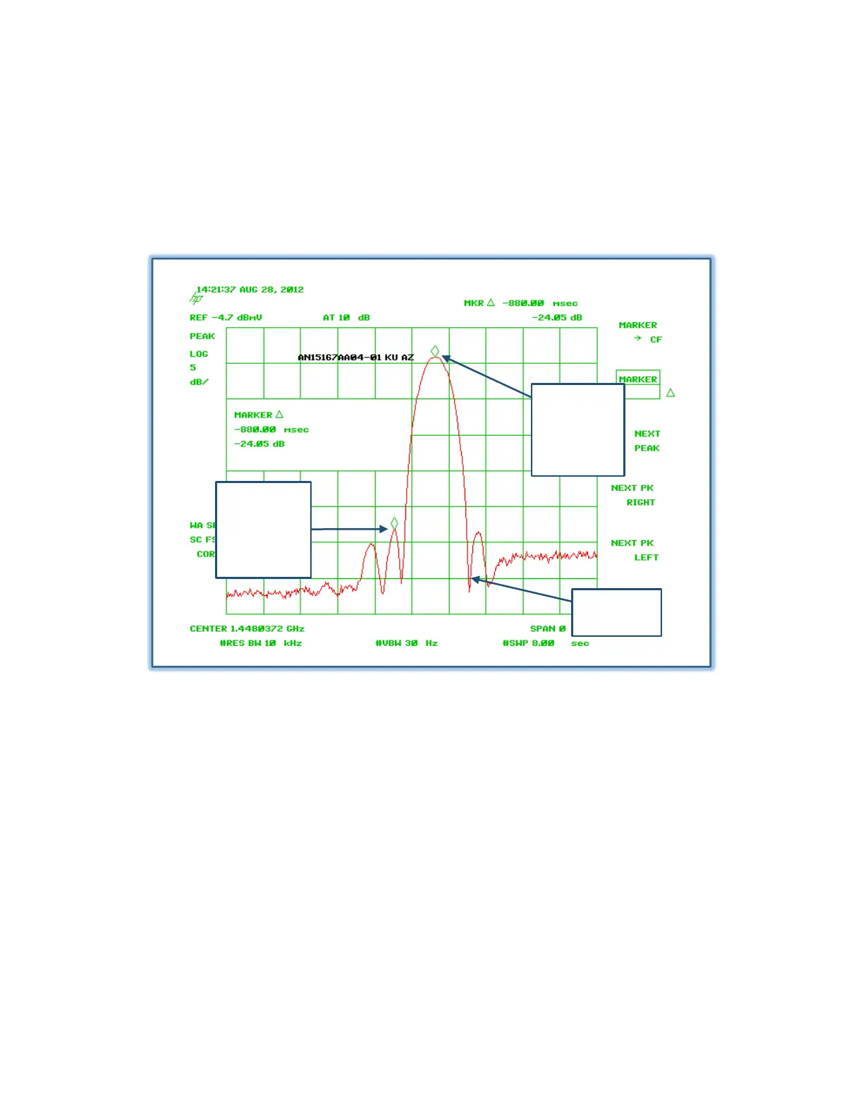
Figure 7.2.3.5 – Antenna Test Receive Pattern Example
7.2.3.6 Feed Bits (Band Sensing)
The AAQ is capable of multiband operation. When using a multi-feed system, the feed bits are
utilized in recognizing the feed selected. Generally the feed connection is located on the
interchangeable feed platform.
Beam