Connector Pin Assignments
DV14307.03 Issue 06 February 2021 Transceivers 6200 Series 57
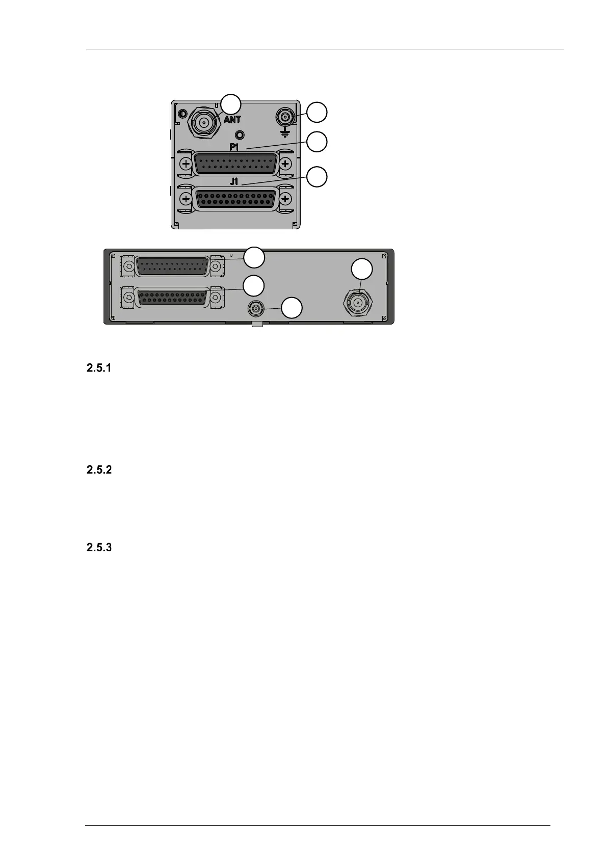
2.5 Connector Pin Assignments
Figure 18: AR62X1, RT62X1 – Connector Layout
2: Grounding bolt
3: P1
4: J1
Figure 19: AR62X3 – Connector Layout
2: Grounding bolt
3: P1
4: J1
Device Connectors (AR62XX, RT62X1)
Position 3 (P1)
• Type: 25pin D-Sub male connector with slide-in fastener.
Position 4 (J1)
• Type: 25pin D-Sub female connector with slide-in fastener.
Antenna Connector (AR62XX, RT62X1)
• The antenna connector is a BNC type.
• The antenna port is made for operating with a nominal impedance of 50 Ω.
Grounding Bolt (AR62XX, RT62X1)
• The transceivers have a M4 threaded grounding bolt at the rear side.
• Use this grounding bolt to make a low impedance grounding of the device.
o Maximum tightening torque for ground stud screw is 1.5 Nm (14 inch-lbs).
o Wire cross section: min. 4 mm
2
.
o Length: max.150 mm (6 in).