Configuration Setup
DV14307.03 Issue 06 February 2021 Transceivers 6200 Series 73
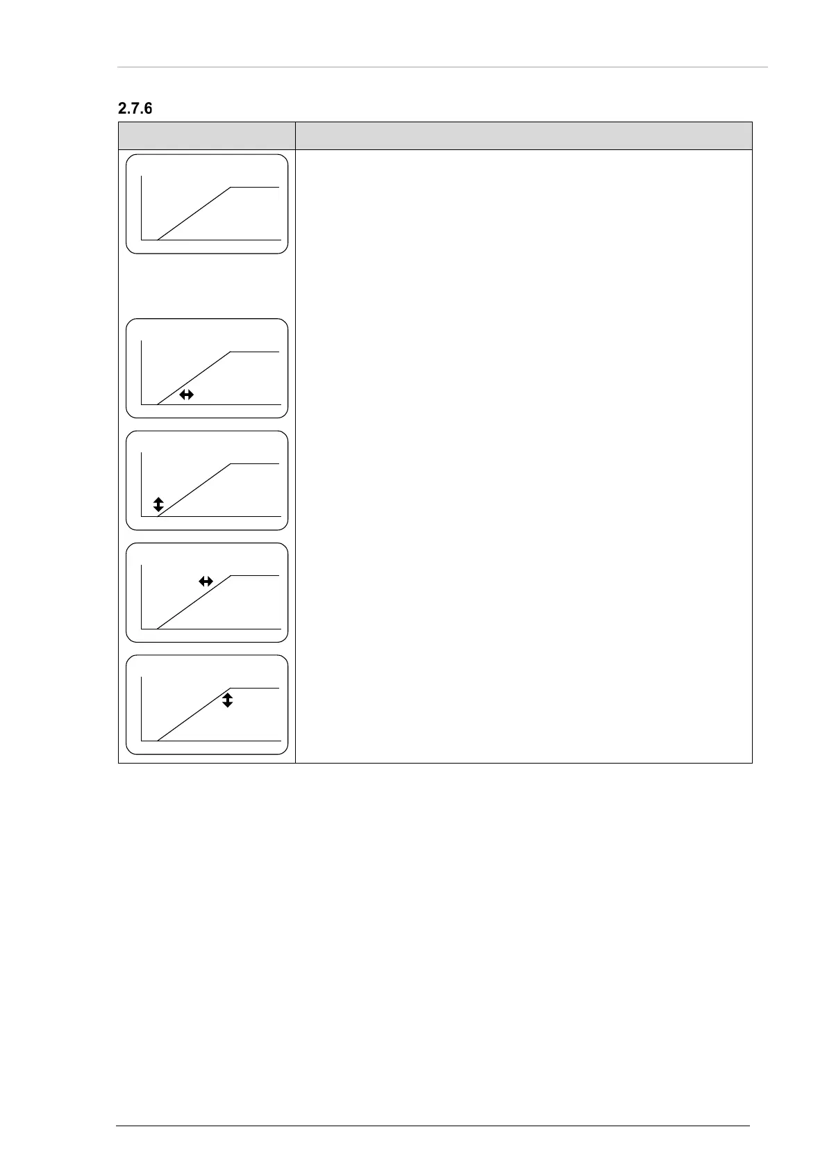
Illumination Curve
Notice: This page is shown only when the the DIMMING input is selected for "14 V or 28 V"
dimming-bus voltage. The menu is available on the primary and secondary controller.
• The illumination curve shows the relation between dimming bus
voltage and brightness of the LCD and key illumination.
• Two adjustable points V1 and V2 define the illumination curve.
• Push the "STO" key to select the parameter.
• Adjust the value in horizontal (left/right), vertical (up/down) direction
• (1) This parameter specifies the horizontal parameter V1x (minimum
values: 1.5 V for 14 V dimming bus and 4 V for 28 V dimming bus).
• Up to this value the brightness is zero.
• When reaching V1x the brightness is immediately adjusted to V1y.
• (2) This parameter specifies the vertical parameter V1y which is the
level of brightness that is set when the trigger point V1x is reached.
• (3) This parameter specifies the horizontal parameter V2x (maximum
values: 14 V or 28 V depending on selected dimming input) where
the illumination curve reaches the maximum brightness level.
• (4) This parameter specifies the vertical parameter V2y which is the
maximum brightness.