54733-10BA2L
2 – 200 02.2017
2 Installation Volume 2
The installation height of the supporting structure that is to be pro-
vided by the customer has to be measured using the dimensional
drawings of the shielding.
The size and stability of the supporting structure or another suit-
able mounting device for the shielding has to match the size and
total weight of the shielding. For safety reasons, every rod source
shielding should in addition be secured against tipping over by a
support bracket (see also Fig. 2-28 on page 2-204). For informa-
tion on dimensions and the weight, for which the fixtures are
designed, please see the technical drawings of the shielding in
chapter 5.
Single part shieldings for rod sources have to be marked top and
bottom to rule out any side-inverted installation (see Fig. 2-26).
The shielding should be installed fairly close to the vessel surface
(or the surface of a thermal insulation), so that the measuring
range covered is not diminished and it is not possible to reach into
the useful beam, which must be prevented for radiation protection
reasons. Fig. 2-26 shows the operator's side, the opposite side
must face the vessel.
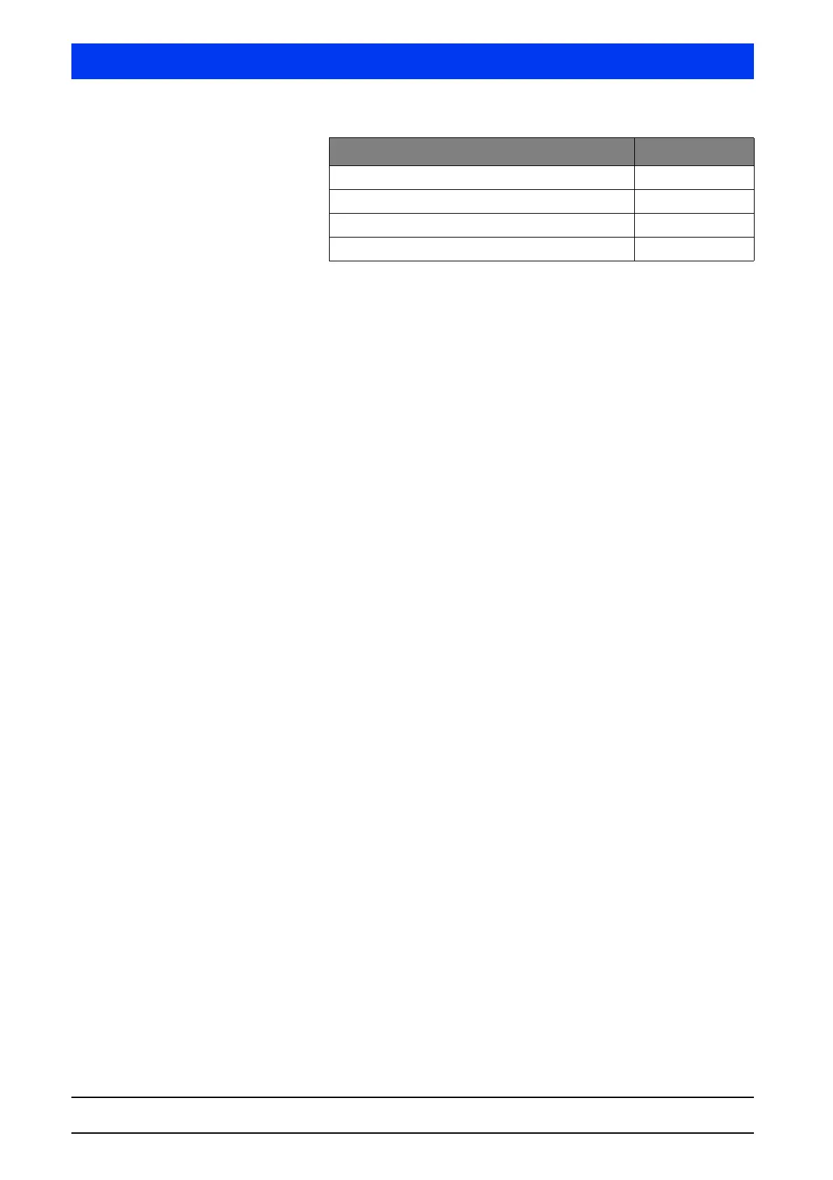
Shielding diameter (in mm) G (in mm)
100 92
150 132
200 169
270 202