54733-10BA2L
2 – 208 02.2017
2 Installation Volume 2
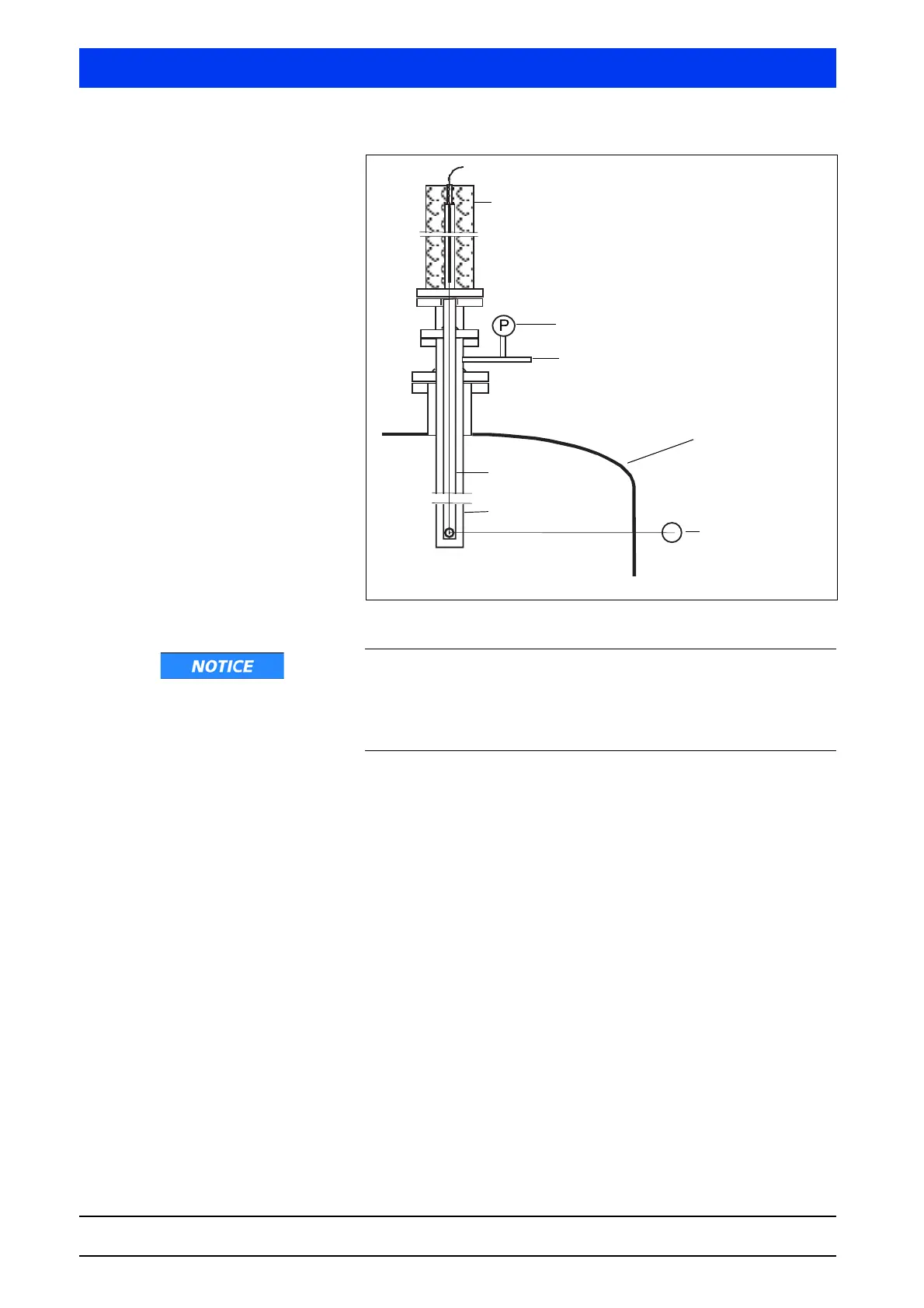
Fig. 2-31 Dip tube installation with point source and point detector
If the shieldings are employed in aggressive atmospheres, the steel
cable or the shaft core and the latch mechanism have to be
checked for corrosion in regular intervals. The intervals between
the checks have to be defined by the operator such that a malfunc-
tion of the mechanism due to corrosion is ruled out.
Version with shaft core
Instead of a steel cable, a shaft core is installed which consists of a
spring wire. This allows you to install flange shieldings to the vessel
from below or from the side and to insert the source from there into
the dip tube and to position it. The shaft core is inserted completely
into the shielding to position the source. The immersion depth of
the source is then fixed by a clamping screw, not with the position-
ing screw. In exceptional cases, it may be necessary, with point
sources, to determine the position accurate to the millimeter to
make sure that the beam path does not hit any vessel installation.
Shielding with
source
Pressure control
Protection gas
Vessel wall
Detector
Dip tube
Protection tube