54733-10BA2L
2 – 224 02.2017
3 Electrical Installation Volume 2
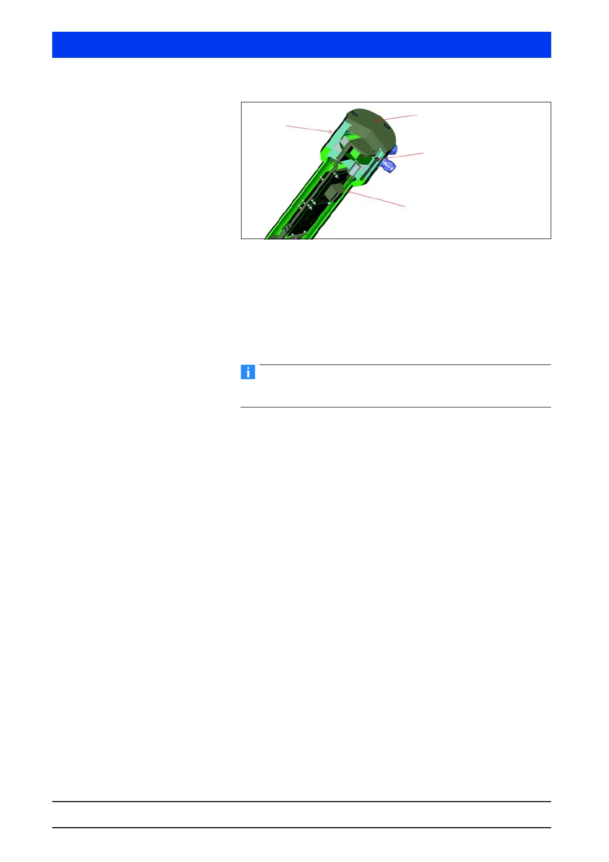
Fig. 3-4 Detector housing with connection head
Connecting cables Unscrew the housing cover (M5 and M8 Allen wrench).
Remove the sealing plug on the bushings that you need for your
cable entry.
Install the screwed cable gland or for FM/CSA a conduit system
with a conduit seal before the cable entry into the terminal
compartment.
In Ex-protected areas, use only cable glands that are approved for
your explosion protection.
Pull the connection cables with the complete external insulation
through the cable entry into the terminal compartment.
Make sure that the cable diameter of the cable used is suitable
for the screw connection.
Make sure when installing the cables that mechanical damage
to the conductor insulation from sharp edges or moving metal
parts will be ruled out.
Keep the cable length long enough to create a cable loop for
strain relief before the housing inlet.
Do not unscrew the 6 screws
connecting the detector
housing to the connection
head.
Detector housing
Housing cover
Connection head