54733-10BA2L
2 – 232 02.2017
4 Repair, Maintenance and Upkeep Volume 2
Risk of fatal injury due to electric shock!
When the housing is open, you may come into contact with live
parts if the power supply is connected.
Make sure when you open the cover that no supply voltage is
applied to the terminals. Use a voltmeter.
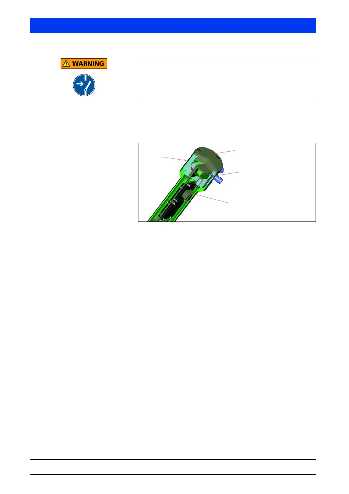
Unscrew the housing cover (M5 and M8 Allen wrench).
Unscrew the six screws that connect the detector housing to
the connection head (Torx T25).
Fig. 4-1 Dismantling the detector electronics
Carefully pull out the electronics module together with the crys-
tal-multiplier assembly.
Remove the overtube with the multiplier (SuperSENS) or the
crystal-multiplier assembly (CrystalSENS) from the electronics.
Loosen the connecting wires between connection head and
electronics.
Remove the electronics from the connection head by opening
the four stud screws on the side of the metal plate of the PCB
holder.
Now you can replace the entire electronics module.
6 screws which connect the
detector housing to the con-
nection head.
Detector housing
Housing cover
Connection head