TECHNICAL
SPECIFICATIONS
2
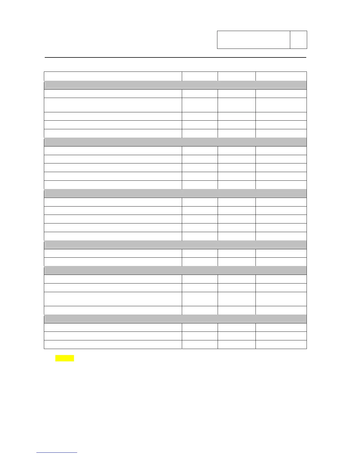
Description Size (mm) Torque (Nm) Notes
SWING ARM
Eccentric clamp fixing screw M8x22 25 Loctite 243
Swing arm plates fixing screw M10x1,25 50
Loctite 243
(grease under head)
Fixing screw of the upper and lower chain slider M4x8 3 Loctite 243
Fixing screw of the side chain slider M4x12 3 Loctite 243
Swing arm pivot fixing screw M16x1,5x20 55 grease under head
FRONT BRAKE SYSTEM
Brake calliper fixing screw M10x1,25x65 45 Grease
Brake bleeding screw M10x1 20/man
Junction screw of brake hoses to calliper and master cylinder M10x1 20
Fixing screw of the master cylinder to handlebar M6x1,25 11
Fixing screw of the brake oil tank to master cylinder M6x10 10 Loctite 243
REAR BRAKE SYSTEM
Fixing screw of the rear brake calliper M8x20 25 Grease
Fixing screw of the rear master cylinder M6x16 10 Loctite 243
Fixing screw of the rear brake oil tank M5x30 5 Loctite 243
Bleeding screw M10x1 20/man
Junction screw of brake hoses to calliper and master cylinder M10x1 20
FRONT WHEEL
Fixing screw of the front wheel pivot M20x1x13 ???? Grease
Fixing screw of the front brake disc to rim M8x18 22 Loctite 243
REAR WHEEL
Fixing screw of the front brake disc to rim M8x20 22 Loctite 243
Fixing screw of the shock absorber flange to rim M8x25 22 Loctite 243
Shock absorber small pivot + rear sprocket fixing nut to
sprocket holder flange
M10x1,25 40
Loctite 243
(grease under head)
Rear wheel pivot M26x2 100 Grease
HANDLEBAR – CLUTCH CONTROL – THROTTLE CONTROL
Fixing screw of semi-handlebar to fork clamp and fork stem M8x30 25 Grease
Rotation screw semi-handlebar to clamp M4x8 3 Loctite 243
Fixing screw of the clutch pump clamp to semi-handlebar M6x25 11
NOTES
The tightening torque must be applied slowly and gradually using a calibrated torque wrench tool.
In case of screwing with automatic impact wrench, the reference torque must be reduced of 10%.
Sub 2-14