General Information 13
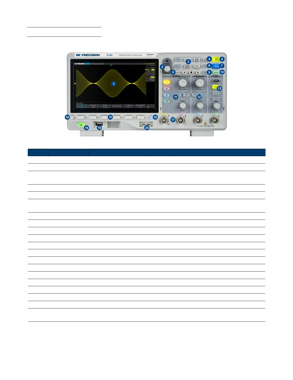
1.5 Front Panel Overview
The front panel interface allows for control of the unit.
Figure 1.4 Front Panel
Item Name Description
1 LCD Display Visual presentation of the device function and measurements.
2 Intensity Adjust Universal knob.
3
Common
Function Keys
Used to invoke the functions displayed above them.
4 Numeric Keypad Used to enter precise values
5 Rotary Knob Used to navigate menus or congure parameters
6 Navigation Keys
Used to navigate menus. The enter key can be used to select a menu or enter a para-
meter
7 CH 2 Terminals Serves as output or input terminals of CH 2 depending on the set functionality
8 Function Keys Frequently used function such as Home, Trig, Menu, ESC, and On/O keys
9 CH 1 Terminals Serves as output or input of CH 1 depending on the set functionality
10 Softkeys Used to invoke any functions displayed above them.
11 Power Switch Power the unit ON or OFF
12 Horizontal Control
13 Auto Set the trigger mode to auto.
14 Menu On/O Enable/disable the menu bar.
15 Softkeys Used to invoke any functions displayed above them.
16 Print Shortcut key for the save function.
17 Input Channels Input channels (1 MΩ BNC)
18 Power Button Power the unit ON or OFF.
19 USB Host Port USB port used to connect ash drives. (Type A)
20
Probe
Compensation
Probe compensation/ground terminal.
Table 1.1 Front Panel