Serial Trigger and Decode 67
7.2 SPI Trigger and Serial Decode
7.2.1 Setup for SPI Signals
Setting the SPI (Serial Peripheral Interface) signal includes two steps: Connecting the CLK, MISO, MISO and CS signal
to oscilloscope, specifying the parameters of each input signal.
1. Touch Decode key to enter the Decode menu.
2. Touch Decode and select the desired slot (Decode1 or Decode2).
3. Touch Protocol softkey, then use the Universal Knob to select SPI.
4. Touch Signal to enter the Signal menu.
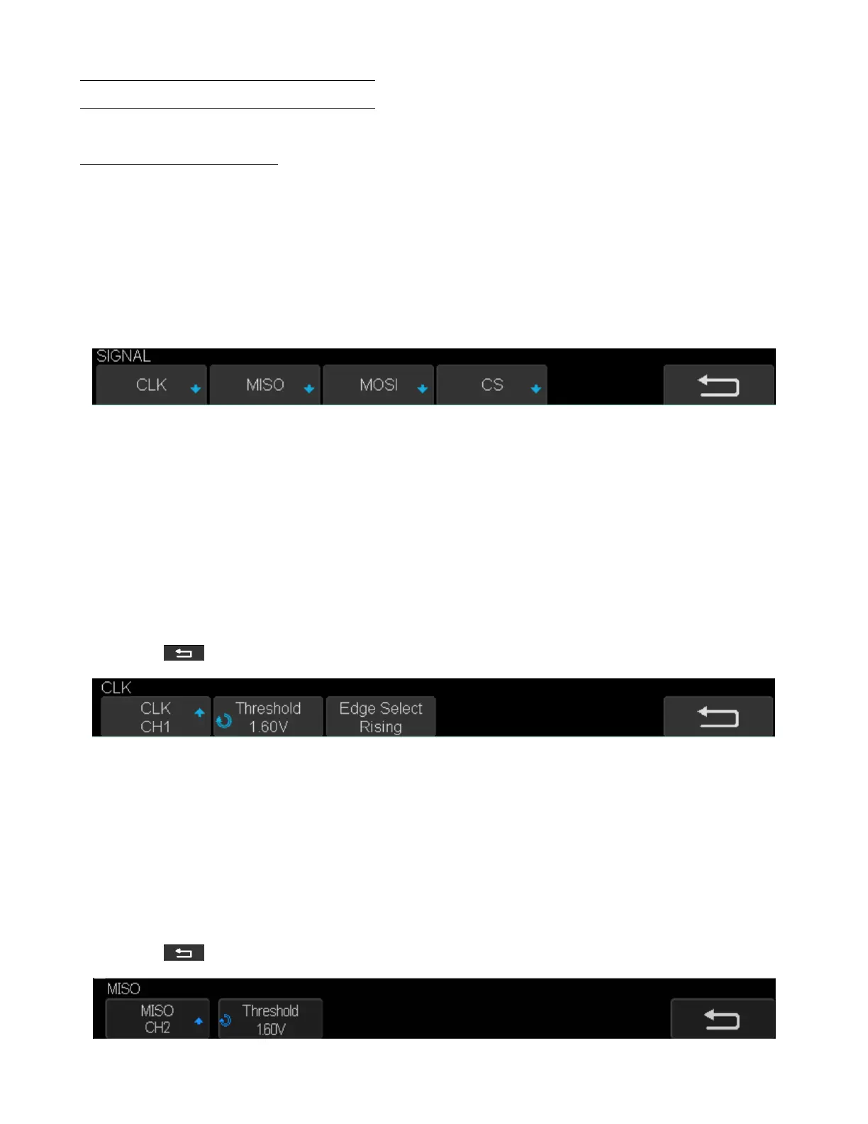
Figure 7.8 Signal Menu
5. Set CLK (clock signal):
• Touch CLK to enter CLK menu.
• Touch CLK to select the channel that is connected to the SPI clock signal.
• Touch Threshold to set the SPI clock signal’s threshold voltage level by Universal Knob.
– The threshold voltage level is for decoding, and it will be regard as the trigger voltage level when set the
trigger type to serial.
• Touch Edge Select to set the oscilloscope will samples at clock signal’s rising edge or falling edge.
• Touch to return previous menu.
Figure 7.9 CLK Menu
6. Set MISO:
• Touch MISO to enter the MISO menu.
• Touch MISO to select the channel that is connected to the SPI MISO signal.
• Touch Threshold softkey, then use the Universal Knob to set the SPI MISO signal’s threshold voltage level.
– The threshold voltage level is for decoding, and it will be regard as the trigger voltage level when set the
trigger type to serial.
• Touch to return to the previous menu.
Figure 7.10 MISO Menu