Serial Trigger and Decode 79
7.4.1 CAN Serial Decode
Upon completing the setup of can signal and trigger, the CAN signals can be decoded.
1. Press Decode –> Decode. Select one of the options from the Decode1 and Decode2.
2. Touch Display and select On to display the result of decoding.
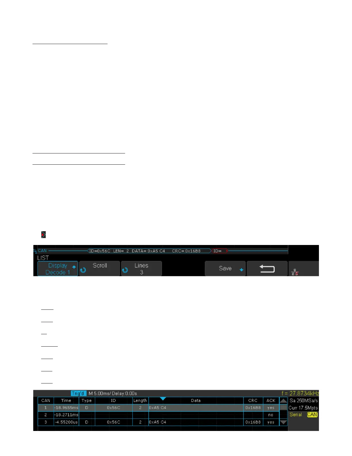
3. Touch List to enter the LIST function menu.
4. Touch Display and choose the same options as the rst step.
5. Touch Lines and set the number of lines by Universal Knob. The range of the lines is 1 to 7.
6. Touch Format softkey to change the character encoding format of the decoder’s result.
7. Touch Scroll and turn the Universal Knob to view all frames.
Interpreting CAN Decode
The frame of decoding result:
• Arbitration eld is displayed in frame
• Control eld is displayed in frame
• Data eld is displayed in frame
• CRC eld is displayed in frame
• Indicates there is not enough space on the display to show complete content of a frame and some content is hidden.
Figure 7.26 CAN Decode Bus Display
The list of decoding result:
• Time — the horizontal displacement between current frame and trigger position.
• Type — the type of frames, “D” represents data frame, “R” represents remote frame.
• ID — the id of frames, the oscilloscope can automatically detect the length of frame’s id (11 bits or 27 bits).
• Length — the length of data eld.
• Data — the value of data eld.
• CRC — the value of CRC (Cyclic Redundancy Check) eld.
• ACK — Acknowledgment bit.
Figure 7.27 CAN Decode List Display