Serial Trigger and Decode 77
7.4 CAN Trigger and Serial Decode
Placed in order of Setup for CAN Signals, CAN Trigger, CAN Serial Decode to trigger and decode the signals.
7.4.1 Setup for CAN Signals
1. Touch Decode key to enter the DECODE function menu.
2. Touch Decode and select the desired slot (Decode1 or Decode2).
3. Touch Protocol and then select CAN by turning Universal Knob.
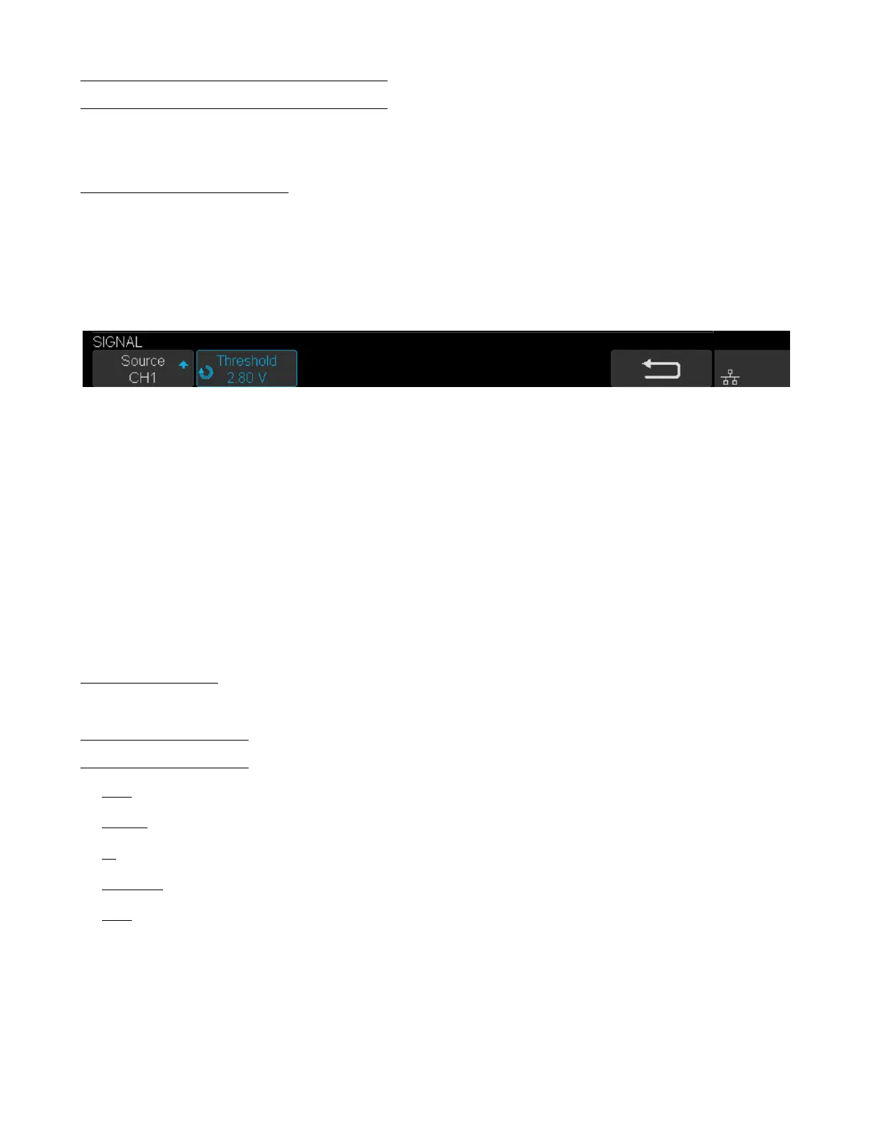
4. Touch Signal to enter the SIGNAL menu as shown in gure ??.
Figure 7.24 CAN Signal Menu
a. Touch Source to select the channel that is connected to the CAN signal.
b. Touch Threshold key to set the CAN signal’s threshold voltage level by Universal Knob. The threshold voltage
level is for decoding, and it will be regard as the trigger voltage level when set the trigger type to serial.
5. Touch Congure to enter the BUS CONFIG menu.
6. Touch Baud to set baud rate by rotating the Universal Knob.
• The baud rate can be set as predened value (from 5kb/s to 1Mb/s) or custom value (from 5kb/s to 1Mb/s).
• If the desired baud rate is not listed, press Baud and select the custom option, press the Custom and turn the
Universal Knob to set the desired baud rate.
7.4.2 CAN Trigger
This section provides a brief introduction and description for the operation of the CAN trigger.
Trigger Conditions
• Start — the oscilloscope will be triggered at the start bit of a frame.
• Remote — the oscilloscope will be triggered by a remote frame with specied ID.
• ID — the oscilloscope will be triggered by a remote or data frame that have specied ID.
• ID+DATA — the oscilloscope will be triggered by data frame that have specied ID and data.
• Error — the oscilloscope will be triggered by an error frame.