Serial Trigger and Decode 68
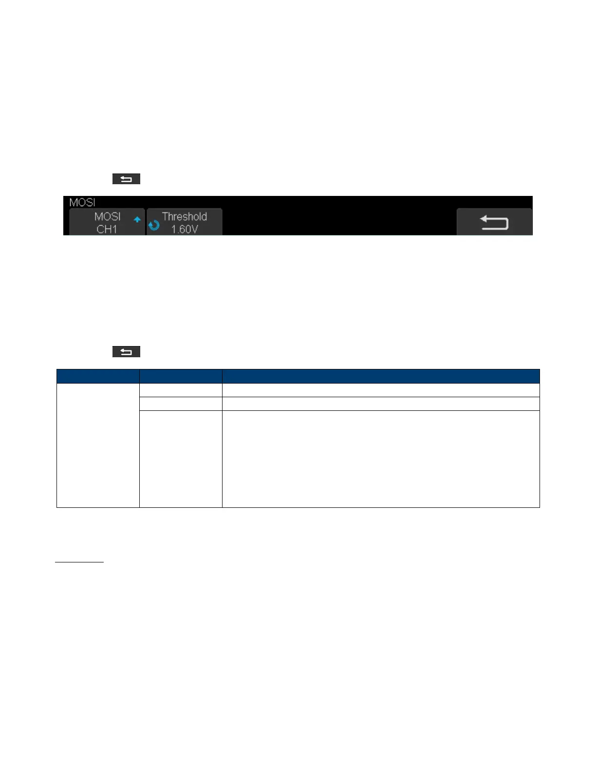
7. Set MOSI:
• Press the MOSI to enter the MOSI menu.
• Touch MOSI to select the channel that is connected to the SPI MOSI signal.
• Press the Threshold softkey, then use the Universal Knob to set the SPI MOSI signal’s threshold voltage level.
– The threshold voltage level is for decoding, and it will be regarded as the trigger voltage level when the trigger
type is set serial.
• Touch to return to the previous menu.
Figure 7.11 MOSI Menu
8. Set CS:
• Touch CS to enter the MOSI menu.
• Touch CS Type to select the chip select type.
• Modify the CD value.
• Touch to return to the previous menu.
Function Menu Settings Description
CS Type
˜CS Low voltage level of CS signal is available
CS High voltage level of CS signal is available
CLK Timeout
If the time between two edges of the clock signal is less than (or equal to)
the value of timeout, the signal between the two edges is treated as a frame.
The range of clock timeout is 100 ns - 5 ms.
This setting is suitable for case where the CS signal is not connected, or the
number of oscilloscope channels is insucient (such as 2-channel
oscilloscopes).
Table 7.1 CS Type Paramters
Example
Connect the data, CLK and ˜CS signals of a SPI bus respectively to C1, C2, and C3. Data width = 8-bit, Bit order =
MSB, CS polarity = CS, and 12 data bytes are transmitted in one frame.
In the SPI trigger signal menu, set the source and threshold of CLK, MISO and CS signals, then copy the trigger settings
to decoding. Adjust the time base, so that the falling edge of the CS signal is shown in the display: