Getting Started 21
Probe Attenuation
Probes are available with various attenuation factors which aect the vertical scale of the signal. The Probe Check
function veries that the probe attenuation option matches the attenuation of the probe.
Press CH 1 once to open the channel menu. Use the softkeys to navigate to page 1/2 and select the Probe option.
Select the probe option that matches the attenuation of the probe.
Note:
The default setting for the Probe option is 1 X.
Verify that the attenuation switch on the probe matches the Probe option in the oscilloscope. Switch settings are 1 X
and 10 X.
Probe Compensation
Before taking any measurements using a probe, verify the compensation of the probe and adjust it to match the channel
inputs.
To match your probe to the input channel:
1. Set the channel’s probe attenuation to 10X.
– Press the CH # key corresponding to the channel the probe is connected to.
– Use the softkeys to navigate to page 1.
– Use the softkeys to select Probe.
– Use the Intensity Adjust knob to select 10X.
2. Attach the probe tip to the Compensation Signal Output Terminal 3 V(Cal) connector and the reference lead to
the Probe Ground terminal connector.
– Press the Auto Setup key to display the square wave.
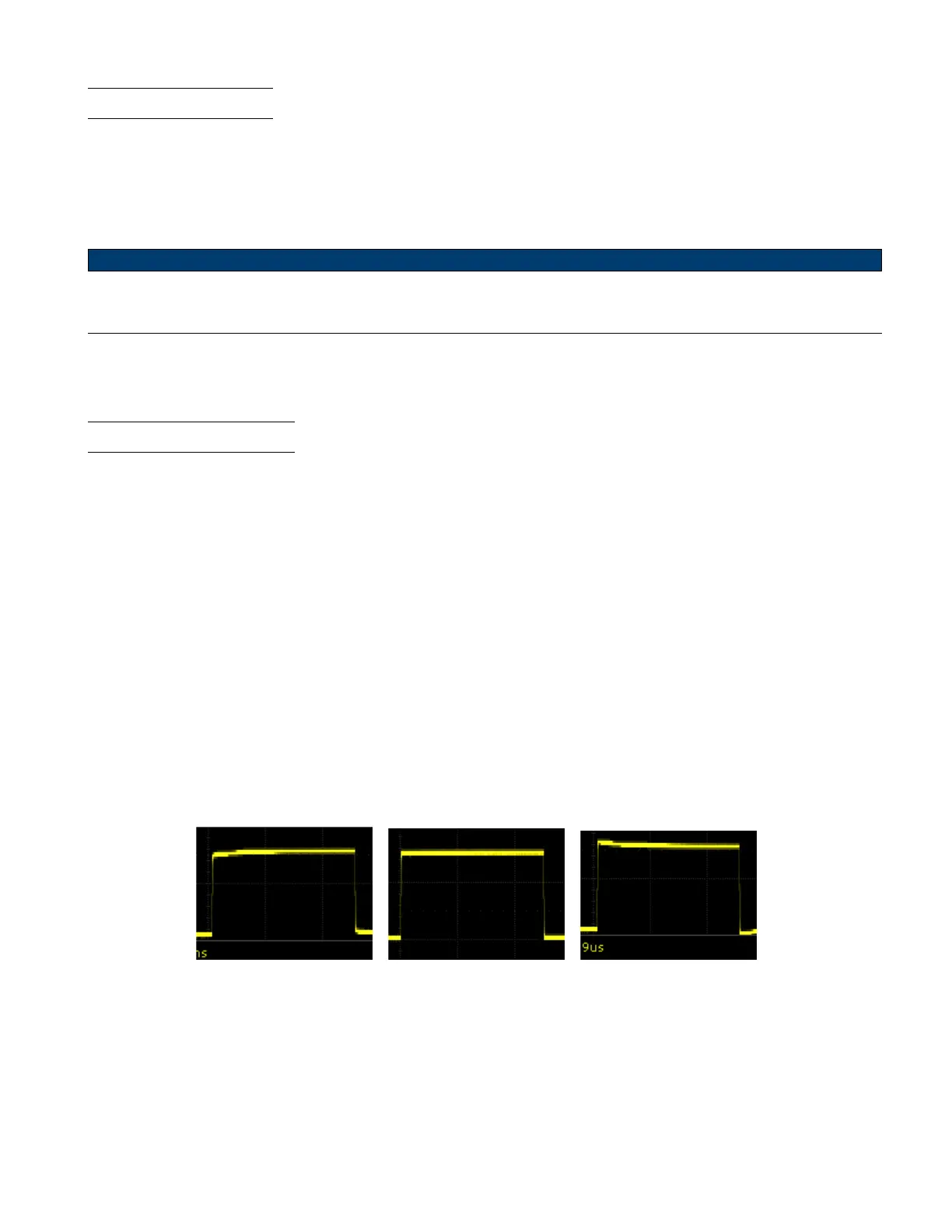
3. Check the shape of the displayed waveform.
Undercompensated Correctly Compensated Overcompensated
Figure 2.5 Probe Compensation
4. If necessary, adjust your probe’s compensation trimmer pot.