Using ATEM Software Control
3 In your camera’s settings, set the camera ID number to match your switcher input.
For example, if studio camera 1 is connected to ‘cam 5’ on your ATEM switcher, the
camera number in your camera settings must also be set to 5. This ensures tally is
sent to the correct camera.
Connect a Blackmagic URSA Mini to any of your ATEM switcher’s SDI inputs,
and the corresponding SDI output back to the camera's program input
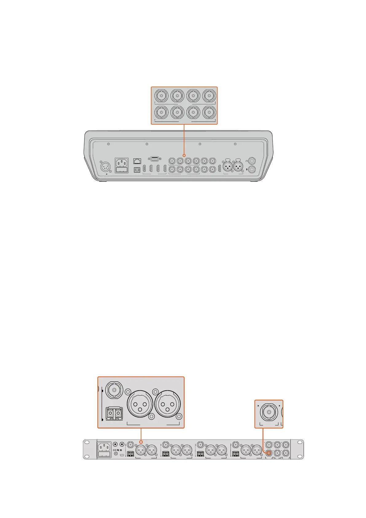
Connecting via Optical Fiber
1 Connect the Blackmagic Camera’s optical out/in to the optical out/in on an
ATEMStudio Converter or ATEM Talkback Converter 4K. You’ll need to have SMPTE
compatible optical fiber SFP modules installed in your Studio Camera and ATEM
converter to connect via optical fiber.
2 Connect a suitable SDI out from your ATEM converter to any SDI input on your
ATEM switcher.
3 Connect any one of your ATEM switcher’s SDI outputs, except the multi view outputs to
your ATEM Converter’s ‘SDI in’. Camera control signals are not sent via the multi view
SDI output.
4 On the Blackmagic camera, open the LCD menu and set the camera number to match
your switcher input. For example, if camera 5 is connected the 'cam 5' SDI input on your
ATEM switcher, your camera number must also be set to 5. This ensures tally is sent to
the correct camera.
Open ATEM Software Control preferences and set your switcher’s button mapping to make sure
you are switching the right camera with correct tally. With a video connection from your switcher
to a Blackmagic camera, you can also get the advantage of live tally indicators, as well as the
camera operators being able to view the program feed of your switcher by pressing the
camera’s ‘pgm’ button.
Connect multiple Blackmagic Studio Cameras via optical fiber using
anATEM Studio Converter. You’ll need to have an optional SFP module
installed in your Studio Camera to connect via optical fiber.
CONTROL
USB 2.0
1 2 3 4
REMOTE
5 6 7 8
5 6 7 8
SDI INPUTSHDMI INPUTS REF IN PGM
SDI OUTPUTS AUX MULTI-VIEW
MULTI-VIEW
PUSH PUSH
CH 1 CH 2
12-30V 3A
CONTROL
USB 2.0
1 2 3 4
REMOTE
5 6 7 8
5 6 7 8
SDI INPUTSHDMI INPUTS REF IN PGM
SDI OUTPUTS AUX MULTI-VIEW
MULTI-VIEW
PUSH PUSH
CH 1 CH 2
12-30V 3A
4321
OPTICAL OUT/IN
SDI OUT
L R
RL
USB 2.0
+12V BACKUP
POWER
OPTICAL OUT/IN
SDI OUT
L R
ANALOG AUDIO OUT OPTICAL OUT/IN
SDI OUT
L R
ANALOG AUDIO OUT OPTICAL OUT/IN
SDI OUT
L
OUT
R
ANALOG AUDIO OUTANALOG AUDIO OUT
IN
PGM SDI
OUT
IN
MIC
OUT
IN
H/PHONE
AES/EBU TALKBACK LOOPS
PUSH
LOCK TO TALK
PRESS TO TALK
63