Performing Transitions using ExternalHardwarePanels
To set network location of multiple switchers on the ATEM 2 M/E Broadcast Panel, simply
follow these steps for each System Control M/E block:
1 When there is no communication with the switcher, the NETWRK SETUP menu will
appear on the broadcast panel system control. Select the NETWRK SETUP menu
button. If there is communication with a switcher, hold down SHIFT and DEST SHIFT
and select the NETWRK SETUP button.
2 Select the SWITCHR IP menu button and use the knobs or the numeric keypad to edit
each field as required.
3 When a field is changed, SAVE and REVERT menu buttons become available.
Select SAVE to save the changed IP address. The system control display will show
it is connecting to the switcher and will display the model of switcher once it has
successfully connected.
This does not change the IP address of the switcher itself. It just changes where the control
panel is looking to find the switcher. If the control panel cannot find the switcher, then you might
need to check the switcher processor to see if it’s been set correctly. To change the IP address
of the switcher, connect the switcher via USB to a computer and run Blackmagic ATEM Setup
software as described previously in this manual.
Performing Transitions using
ExternalHardwarePanels
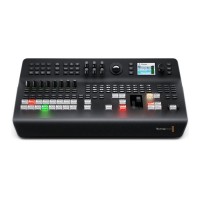
The buttons and knobs on the ATEM 1 M/E and 2 M/E Broadcast Panels follow the same
M/Elayout, plus the system control blocks share the same functions. This means controlling
your switcher is intuitive when working with both broadcast panels because they operate your
switcher in exactly the same way.
The ATEM 1 M/E Advanced Panel is similar to the broadcast panels with all the same
M/Econtrols. However, the advanced panel uses a large LCD with soft control knobs and
buttons which lets you adjust settings dynamically as you control your switcher. This is a fast
and convenient way of working with your panel.
This section describes how to perform the various transition types on your switcher using an
external ATEM hardware panel.
Cut Transitions
The cut is the most basic transition that can be performed on the switcher. In a cut transition the
program output is immediately changed from one source to another.
Program output for a cut transition.
A cut transition can be performed directly from the program bus, or using the CUT button in the
transition control block.
197