11.15
11 34 004
# Checking valve clearances
– Remove left and right service covers
a
....................................................See Group 46
– Swivel out powertrain cradle (
a
11.12)
– Remove cylinder head cover (
a
11.34)
– Remove spark plug (
a
12.5)
•
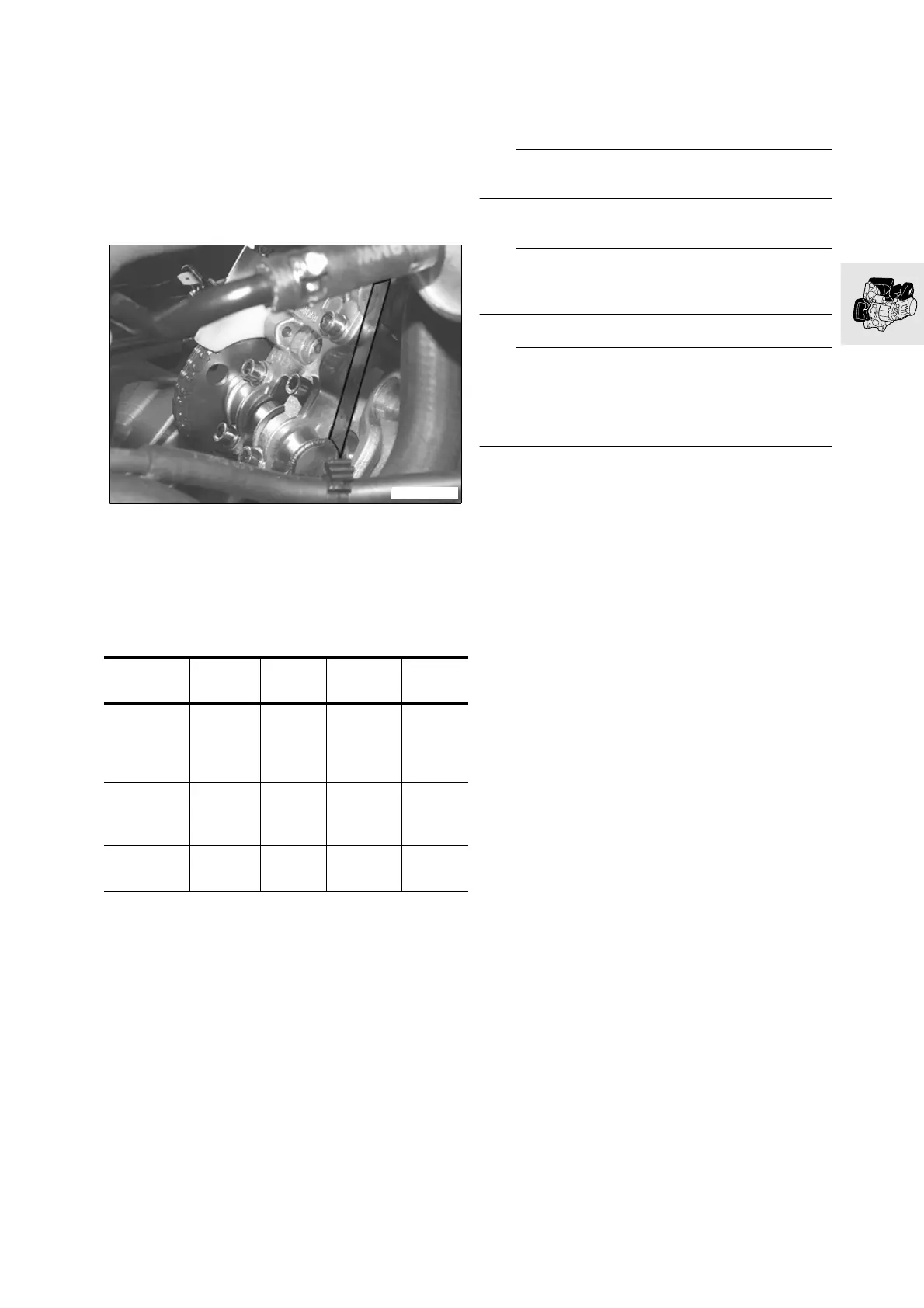
Turn over engine at camshafts, continuing until
the lobes are pointed outward
•
Measure valve clearance using single feeler
gauge blade
•
Record the valve clearances
•
and adjust valve clearance as necessary (replace
tappets) (
a
11.16)
Adjustment data:
Inlet valve clearance........................0.05…0.14 mm
................................................ (0.0019…0.0055 in)
Exhaust valve clearance ..................0.20…0.29 mm
.................................................. (0.0079 0.0114 in)
When installing:
•
Install the cylinder head cover before installing
the powertrain cradle
e
Attention:
Make sure that gasket and cover are free of oil!
•
Installing cylinder head cover
e
Attention:
When lowering watch the struts and the duct to the
intake-air plenum chamber!
L
Note:
Make sure that detent for long lever of the easy-lift
mechanism engages! If necessary, move the lever to
the drive position first, and then move it to the park
position!
•
Swiveling powertrain cradle back
X
Tightening torque:
Cylinder head cover ..................................... 10 Nm
Strut, lower .................................................. 21 Nm
IV left
mm (in)
IV right
mm (in)
EV left
mm (in)
EV right
mm (in)
Spec.
clearance
0.05
0.14
(0.0019
0.0055)
0.05
0.14
(0.0019
0.0055)
0.20
0.29
(0.0079
0.0114)
0.20
0.29
(0.0079
0.0114)
Clearance,
measured
(used)
0.15
(0.0059)
0.15
(0.0059)
Difference
0.01
(0.00039)
-0.05
(-0.00197)
C1111001C1000170