3-24 2002 Buell P3: Engine
HOME
8. See Figure 3-43. Remove lower rocker cover.
NOTE
Remove lower rocker box as an assembly; then disassemble
as required.
9. Mark the location and orientation (top/bottom) of each
push rod. Remove push rods.
CAUTION
Mark rocker arm shafts for reassembly in their original
positions. Valve train components must be reinstalled in
their original positions to prevent accelerated wear and
increased valve train noise.
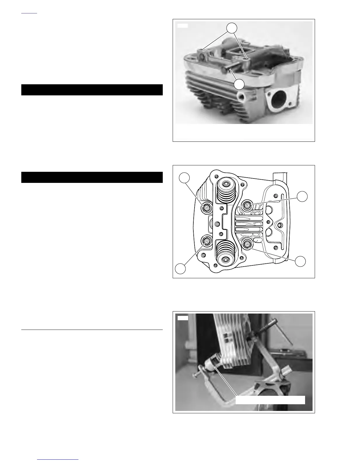
10. See Figure 3-44. Remove rocker arm shafts by tapping
them out using a hammer and a soft metal punch.
11. See Figure 3-43. Remove rocker arms; mark them for
reassembly in their original locations.
CAUTION
Distortion to the head, cylinder and crankcase studs may
result if head screws are not loosened (or tightened)
gradually in the sequence shown in Figure 3-45.
12. See Figure 3-45. Loosen each head screw 1/8-turn fol-
lowing the sequence shown.
13. Support motorcycle under crankcase. Do not allow
engine to drop when performing the next Step.
14. Continue loosening in 1/8-turn increments until screws
are loose. Remove head screws.
15. Remove cylinder head, head gasket, and O-rings.
16. Discard head gasket.
17. See Figure 3-43. Remove push rod cover, gasket and
valve tappets.
DISASSEMBLY
1. See Figure 3-46. Compress valve springs with VALVE
SPRING COMPRESSOR (Part No. HD-34736B).
2. See Figure 3-47. Remove valve keepers, upper collar
and valve springs. Mark valve keepers for reassembly in
their original locations.
3. Use a fine tooth file to remove any burrs on the valve
stem at the keeper groove.
4. Mark valve to ensure that it will be reassembled in the
same head. Remove valve, valve stem seal and lower
collar.
5. Repeat the above procedure for the other valve.
Figure 3-44. Removing Rocker Arm Shafts (Typical)
Figure 3-45. Head Screw Loosening/Tightening
Sequence
Figure 3-46. Valve Spring Compressor
(Part No. HD-34736B)
5698
2
1. Position of rocker arm retaining bolts
2. Retaining notch
1
1
3
4
2
a0128x3x
5694
Valve Spring Compressor