2-28 2002 Buell P3: Chassis
HOME
REAR BRAKE MASTER CYLINDER 2.13
REMOVAL
1. See Figure 2-42. Drain brake fluid into a suitable con-
tainer. Discard used fluids according to local laws.
a. Remove cap from rear caliper bleeder valve. Open
bleeder valve (metric) about 1/2 turn.
b. Install a length of plastic tubing over caliper bleeder
valve. Place free end in a suitable container.
c. Pump brake pedal to drain brake fluid.
d. Tighten bleeder valve (metric) to 3-5 ft-lbs (4-7 Nm).
Reinstall cap.
CAUTION
Damaged banjo bolt surfaces will leak when reassem-
bled. Prevent damage to seating surfaces by carefully
removing brake line components.
2. See Figure 2-43. Remove banjo bolt (1) (metric) and two
banjo washers (2) to detach brake line (3) from master
cylinder (4). Discard banjo washers.
3. See Figure 2-43. Disconnect push rod from brake pedal
clevis (11).
a. Spin locknut (10) away from top surface of clevis.
b. Turn rod adjuster (7) to free rod from clevis (11).
4. See Figure 2-44. Remove two screws (2) and spacers
(3) to detach master cylinder from footrest support.
5. See Figure 2-45. Detach remote reservoir.
DISASSEMBLY
NOTE
Do not disassemble master cylinder unless problems are
experienced. Discard all seals during the disassembly proce-
dure. Install a complete rebuild kit upon assembly.
1. See Figure 2-46. Slide rubber boot on rod assembly (3)
away from master cylinder body (1).
2. Depress rod assembly (3) and remove internal snap ring
(2). Discard snap ring.
3. Remove piston assembly (4) from master cylinder body.
Figure 2-42. Rear Caliper Bleeder Valve (Metric)
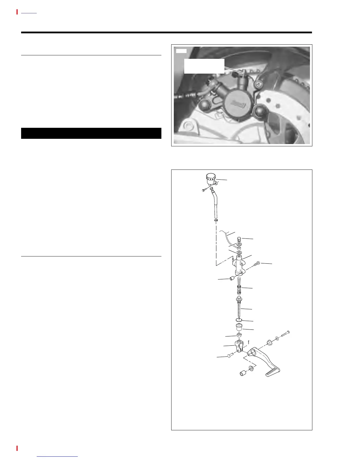
Figure 2-43. Rear Master Cylinder Assembly
7723
Bleeder Valve
(metric)
1
2
6
8
7
9
10
11
13
a0123x2x
1. Banjo Bolt (metric)
2. Banjo Washers (2)
3. Brake Line
4. Master Cylinder
5. Screw (2) (metric)
6. Piston Assembly
7. Push Rod
8. Snap Ring
9. Rubber Boot
10. Locknut
11. Clevis
12. Clevis Pin
13. Remote Reservoir
14. Spacer (2)
3
4
5
12
14