7-58 2002 Buell P3: Electrical
HOME
FUSES AND CIRCUIT BREAKERS 7.24
GENERAL
Buell motorcycles feature two components which protect the
electrical system; Fuses and Circuit Breakers.
Fuses
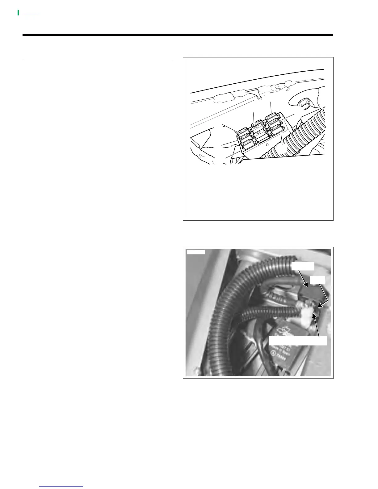
See Figure 7-81. The fuse block is on the right side of the
frame under the seat. The block contains five replaceable
fuses. Two spare fuses (4) are attached to the fuse block.
The lights (1) key switch (2) and system (3) fuses are each
rated at 15 amperes. The ignition (5) and accessory (6) fuses
are rated at 7.5 amperes.
Remove fuses by pulling them straight up and out of the fuse
block. Inspect metal strip inside opaque plastic shell. A bro-
ken metal strip indicates a blown fuse. Always replace fuses
with fuses of the same amp rating.
Always investigate the cause of blown fuses before replacing
them. See your Buell dealer for more information.
Circuit Breakers
See Figure 7-82. The 30 ampere main circuit breaker is under
the seat next to the battery.
Since the circuit breaker is the automatic-reset type, the
bimetallic breaker contacts automatically close (completing
the circuit) once they have cooled down from the initial over-
load. If the overload condition still exists, the breaker contacts
will again open to interrupt current flow. This opening and
closing of the breaker contacts continues as long as the cur-
rent circuit overload condition exists.
To replace the circuit breaker:
1. Remove seat. See 2.28 SEAT.
2. Disconnect battery negative cable from battery.
3. Remove acorn nuts, nuts with lock washers and wire
leads from circuit breaker studs. Tag wire leads for ease
of assembly.
4. Remove circuit breaker from circuit breaker bracket by
carefully prying clip tab, located on left side, open and
sliding circuit breaker out. NOTE: Bank Angle Sensor will
require reinstallation if bracket is removed. See 7.5
BANK ANGLE SENSOR.
5. Install in the reverse order. Tighten screw (if bracket was
removed) to 25-27 in-lbs (2.8-3.1 Nm). Tighten metal nut
to 15-18 in-lbs (1.7-2 Nm). Tighten plastic acorn nuts to
1-3 in-lbs (0.1-0.3 Nm).
Figure 7-81. Fuse Block
Figure 7-82. Circuit Breaker
1. Lights 15A
2. Key Switch15A
3. System 15A
4. Spare (2)
5. Ignition 7.5A
6. Accessory 7.5A
a0072aox
1
2
3
4
4
5
6
7811
Bracket
Circuit Breaker (30A)
Tab