6-12 2002 Buell P3: Drive/Transmission
HOME
CLUTCH RELEASE MECHANISM 6.5
NOTE
For clutch adjustment procedure, See 6.4 CLUTCH.
DISASSEMBLY
1. Remove seat. See 2.28 SEAT.
11WARNING1WARNING
To protect against shock and accidental start-up of vehi-
cle, disconnect the negative battery cable before pro-
ceeding. Inadequate safety precautions could result in
death or serious injury.
2. Disconnect negative battery cable.
3. Pull clutch cable ferrule (end of cable housing) away
from clutch hand lever bracket. Gap between ferrule and
bracket should be 0.0625-0.125 (1.6-3.2 mm). Adjust
freeplay by turning cable adjuster.
4. Remove left footpeg support bracket. See 2.21 FOOT-
PEGS AND FOOTPEG SUPPORT BRACKETS.
5. See Figure 6-16. Remove three TORX screws with
washers and clutch inspection cover.
6. Slide spring with attached screw lockplate from flats of
adjusting screw.
7. Turn adjusting screw clockwise to release ramp and cou-
pling mechanism. As the adjusting screw is turned, ramp
assembly moves forward. Unscrew nut from end of
adjusting screw.
CLEANING AND INSPECTION
1. Thoroughly clean all parts in cleaning solvent.
2. See Figure 6-16. Inspect three balls of release mecha-
nism and ball socket surfaces of inner and outer ramps
for wear, pitting, surface breakdown and other damage.
Replace parts as necessary.
3. Check hub fit of inner and outer ramps. Replace ramps if
excessively worn.
4. Check clutch cable for frayed or worn ends. Replace
cable if damaged or worn.
5. Change or add transmission fluid if necessary. See 6.4
CLUTCH.
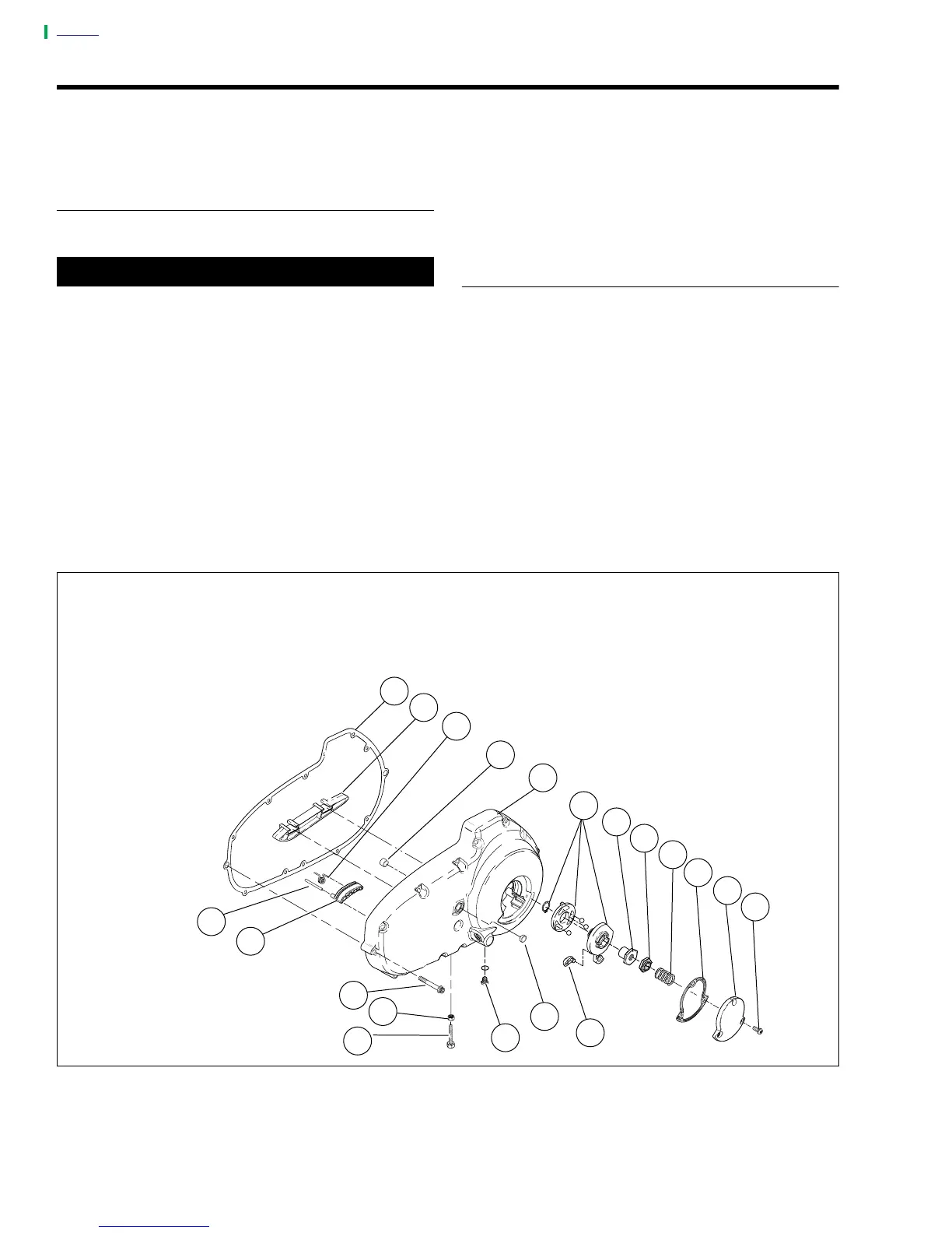
Figure 6-16. Clutch Release Mechanism
a0105x6X
1. TORX Screw with Washers (3)
2. Clutch Inspection Cover
3. Clutch Cover Gasket
4. Spring
5. Lockplate
6. Nut
7. Ramp Assembly
8. Primary Cover
9. Bushing
10. Spring
11. Chain Guide
12. Primary Cover Gasket
13. Pin
14. Shoe
15. Screw
16. Locknut
17. Limiting Screw
18. Drain Plug and O-ring
19. Seal
20. Coupling
1
2
3
4
5
6
7
10
13
12
17
15
14
8
9
11
16
20
19
18