2002 Buell P3: Drive/Transmission 6-11
HOME
ADJUSTMENT
Check clutch adjustment:
●
At the 1000 mile (800 km) service interval.
●
At every 5000 mile (8000 km) service interval thereafter.
If clutch slips under load or drags when released, first check
control cable adjustment. If cable adjustment is within specifi-
cations, adjust clutch mechanism as described below.
When necessary, lubricate cable with LUBIT-8 TUFOIL
®
CHAIN AND CABLE LUBE (Part No. HD-94968-85TV).
1. Raise rear wheel off floor using REAR WHEEL SUP-
PORT STAND (Part No. B-41174).
2. Remove left footpeg support bracket. See 2.21 FOOT-
PEGS AND FOOTPEG SUPPORT BRACKETS.
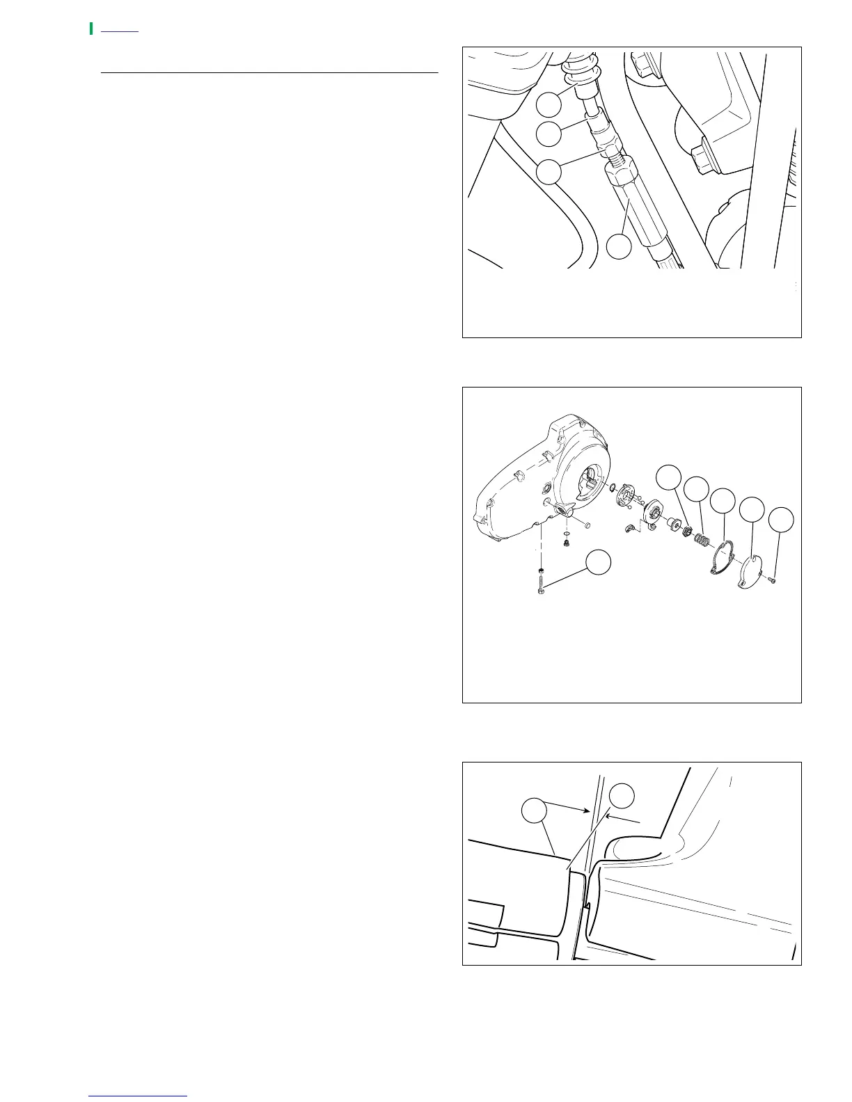
3. See Figure 6-13. Slide rubber boot (1) upward to expose
adjuster mechanism. Loosen jam nut (3) from adjuster
(4). Turn adjuster to shorten cable housing until there is a
large amount of freeplay at clutch hand lever.
4. See Figure 6-14. Remove three TORX screws with
washers (1) from clutch inspection cover (2). Remove
clutch inspection cover from primary cover.
NOTE
Quad ring removed from primary cover for illustrative pur-
poses only in Figure 6-14.
5. Remove spring (4) and lockplate (5). Turn adjusting
screw (6) counterclockwise until it lightly bottoms.
6. Turn adjusting screw (6) clockwise 1/4 turn. Install lock-
plate (5) and spring (4) on adjusting screw flats. If hex on
lockplate does not align with recess in outer ramp, rotate
adjusting screw clockwise until it aligns.
7. Squeeze clutch hand lever to maximum limit three times.
This sets the ball and ramp mechanism. Pull outer cable
conduit and at the same time adjust cable adjuster to
provide 0.0625-0.125 in. (1.6-3.2 mm) freeplay at clutch
hand lever. Adjust as follows.
a. See Figure 6-15. Pull ferrule (1) (end of cable hous-
ing) away from bracket (2). Gap between ferrule and
bracket should be 0.0625-0.125 in. (1.6-3.2 mm).
b. See Figure 6-13. Set freeplay by turning adjuster
(4).
c. Tighten jam nut (3) against adjuster (4).
d. Slide boot (1) over cable adjuster mechanism.
8. Change or add transmission fluid if necessary.
NOTE
Clean parts before re-assembly.
9. See Figure 6-14. Install clutch inspection cover and
new
gasket with three TORX screws with washers. Tighten in
a crosswise pattern to 7-9 ft-lbs (10-12 Nm).
10. Check clutch cable freeplay. See Step 6 above.
11. Install footpeg support bracket. See 2.21 FOOTPEGS
AND FOOTPEG SUPPORT BRACKETS.
Figure 6-13. Clutch Cable Adjuster Mechanism
Figure 6-14. Clutch Release Mechanism
Figure 6-15. Adjusting Clutch Freeplay
1. Rubber Boot
2. Cable End
3. Jam Nut
4. Adjuster
a0159x6x
4
2
1
3
1. Torx Screw
2. Clutch Inspection Cover
3. Quad Ring
4. Spring
5. Lockplate
6. Adjusting Screw
a0155x6x
2
1
3
4
5
6
1. Ferrule
2. Bracket
a0158x6x
2
1