2002 Buell P3: Drive/Transmission 6-39
HOME
TRANSMISSION INSTALLATION 6.14
INSTALLATION
NOTES
● If only transmission components were serviced, the fly-
wheel assembly should already be in place.
● If flywheels and crankcases were serviced, install the fly-
wheel assembly before re-installing the transmission
assembly.
Verify that all parts have been properly installed, as described
earlier in this section under:
● 6.11 MAIN DRIVE GEAR
● 6.10 TRANSMISSION ASSEMBLY
● 6.13 LEFT CRANKCASE BEARINGS
● 6.12 RIGHT TRANSMISSION CASE BEARINGS
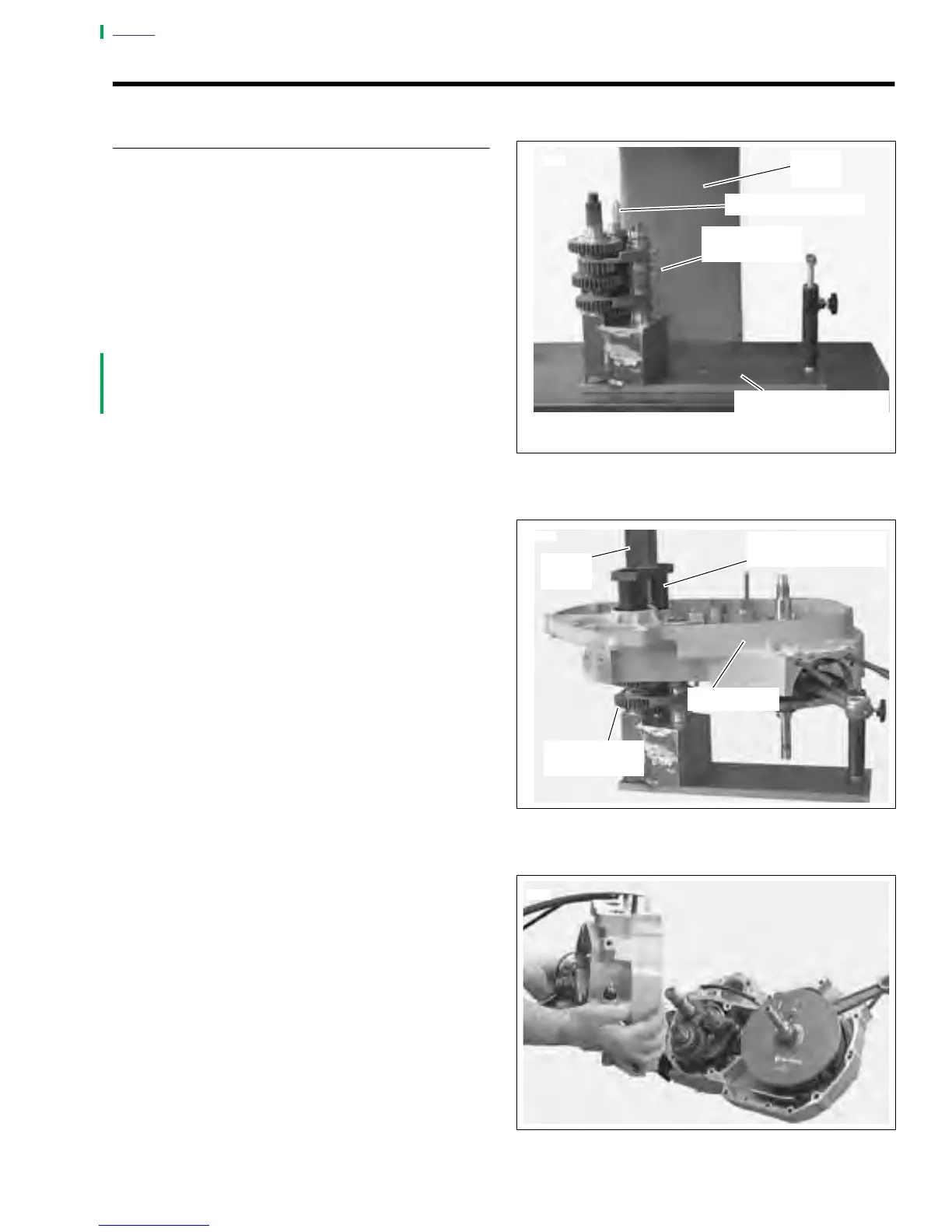
1. Remove left crankcase half from engine stand.
2. See Figure 6-56. Place transmission assembly onto
TRANSMISSION REMOVER/INSTALLER FIXTURE
(Part no. B-43985-2) on arbor press.
a. Install Countershaft GUIDE (Part No. B-43985-4).
b. See Figure 6-57. Install TRANSMISSION
INSTALLER (Part no. B-43985-3) into crankcase.
3. See Figure 6-57. Press crankcase into transmission
assembly until it bottoms out.
4. Remove transmission assembly and left crankcase half
from fixture.
5. See Figure 6-58. Assemble crankcase halves together.
a. Apply a thin coat of DOW CORNING SILASTIC or 3-
M 800 sealant to crankcase joint faces.
b. See CRANKCASE HALVES. Attach crankcase
halves in torquing sequence shown.
c. Apply several drops of LOCTITE
®
thread locker 262
(red) to last few threads.
d. Tighten 1/4-in. fasteners to 80-110 in-lbs (9.0-
12.4 Nm)
e. Tighten 5/16-in. fasteners to 15-19 ft-lbs (20-
25 Nm).
Figure 6-56. Transmission Assembly
Figure 6-57. Transmission Remover/Installer on Fixture
Figure 6-58. Crankcase Halves
7740
Arbor
Press
Guide (B-43985-4)
Transmission
Assembly
Transmission Remov
Installer Fixture
(B-43985-2)
7741
Arbor
Press
Transmission
Installer (B-43985-3)
Crankcase
Transmission
Assembly
7694