2002 Buell P3: Drive/Transmission 6-43
HOME
TRANSMISSION SPROCKET 6.16
REMOVAL
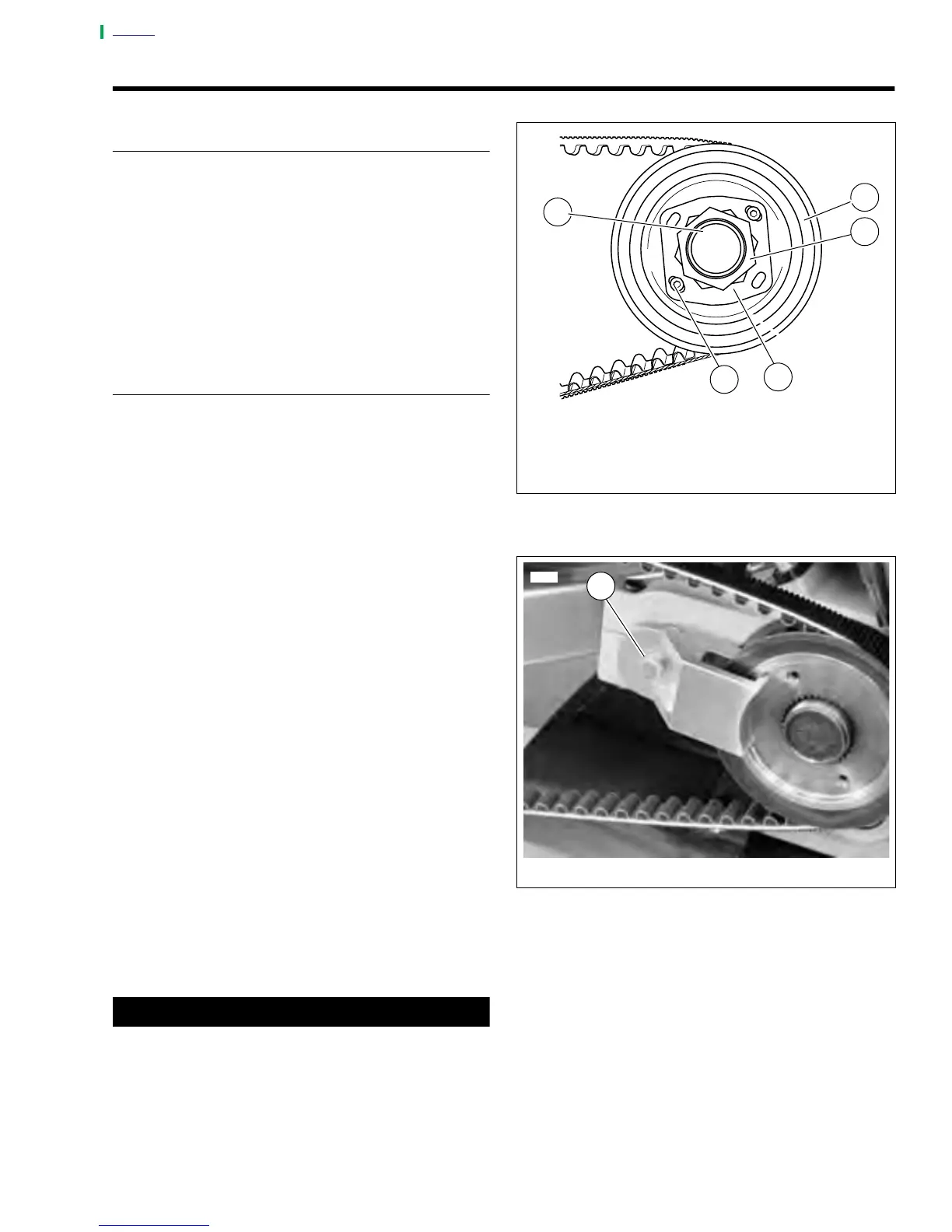
1. See Figure 6-63. Place transmission in first gear.
Remove two socket head screws (5) and lockplate (4).
NOTE:
Transmission sprocket nut has left-hand threads. Turn nut
clockwise to loosen and remove from main drive gear shaft.
2. See Figure 6-63. Remove transmission sprocket nut (3)
from main drive gear shaft (1).
a. See Figure 6-64. Secure pulley using SPROCKET
LOCKING TOOL (1) (Part No. B-43982).
INSTALLATION
1. See Figure 6-63. Install transmission sprocket (2) with
secondary drive belt onto main drive gear shaft (1).
2. Place transmission in neutral.
3. Apply a few drops of LOCTITE
®
thread locker 262 (red)
to the left-hand threads of transmission sprocket nut
(3). Position nut with washer-faced side facing transmis-
sion sprocket. Turn the nut counterclockwise to install it
onto main drive gear shaft.
a. See Figure 6-64. Install SPROCKET HOLDING
TOOL (1) (Part No. B-43982) as shown.
b. See Figure 6-65. Use MAINSHAFT LOCKNUT
WRENCH (Part No. HD-94660-37B) and a torque
wrench to tighten sprocket nut to 50 ft-lbs (68 Nm)
INITIAL torque, ONLY.
c. See Figure 6-66. Scribe a line on the transmission
sprocket nut and continue the line on the transmis-
sion sprocket as shown.
d. Tighten the transmission sprocket nut an additional
30°-40°.
e. See Figure 6-63. Install lockplate over nut so that
two of lockplate’s four drilled holes (diagonally oppo-
site) align with sprocket’s two tapped holes.
NOTE
The lockplate has four screw holes and can be turned to
either side, so you should be able to find a position without
having to additionally tighten the nut. If you cannot align the
screw holes properly, the nut may be additionally TIGHT-
ENED until the screw holes line up, but do not exceed 45° as
specified above. Never LOOSEN nut to align the screw holes.
f. See Figure 6-66. If lockplate will not align with holes,
tighten nut to 45° maximum.
CAUTION
Maximum allowable tightening of sprocket nut is 45° of
counterclockwise rotation, after initially tightening to 50
ft-lbs. Do not loosen sprocket nut while attempting to
align the screw holes. If you cannot align lockplate and
sprocket screw holes, nut may be additionally tightened
45° as specified above. Tightening too much or too little
may cause the nut to come loose during vehicle opera-
tion.
Figure 6-63. Transmission Sprocket
Figure 6-64. Sprocket Locking Tool
1. Main Drive Gear Shaft
2. Transmission Sprocket
3. Transmission Sprocket Nut (left-hand threads)
4. Lockplate
5. Socket Head Screw (2)
a0149x6x
1
2
3
4
5
7398
1. Sprocket Locking Tool (Part No. B-43982).
1