2002 Buell P3: Electrical 7-67
HOME
INDICATORS 7.28
GENERAL
Indicators are Light Emitting Diodes (LEDs) located in the
speedometer. LEDs are non-repairable. Replace the speed-
ometer if an LED fails.
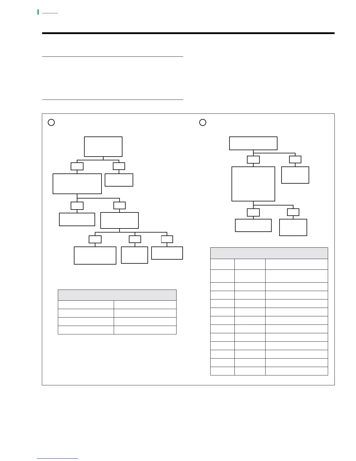
DIAGNOSTICS
See diagnostic tables below.
Indicator Lights
Problem: Light(s) inoperative.
Follow the diagnostic flow charts below. If replacement is
necessary, replace speedometer. See 7.25 ELECTRONIC
SPEEDOMETER.
Figure 7-94. Diagnostics
Ground Present at Pin
7 of Connector [20A]?
Oil Pressure or Neutral Indicator High Beam or R/L Turn Signal Indicator
Check for 12V at
Pin 6 of Connector
[20A]. Is 12V
Present?
Replace
Speedometer.
Is 12V Present when
Circuit is Active?
NOTE
Use Pin 4 (Left Turn),
Pin 2 (Right Turn) and
Pin 3 (High Beam).
Locate and
Repair Open
in Circuit.
Replace
Speedometer.
Instrument Connector [20]
Terminal Wire Color Indicator
1Orange/
White
Power
2BrownRight Turn
3 White High Beam
4Violet Left Turn
5Tan Neutral
6Green/Yellow Oil Pressure
7Black Right/Left Turn/High Beam
8 Not Used Not Used
9 Red Sensor Power
10 White Sensor Return
11 Black Sensor Ground
12 Not Used Not Used
Replace Oil
Pressure
Switch.
Repair Open in GN/Y
Wire (Oil psi) or TN
Wire (Neutral).
5161
Replace
Neutral Switch.
Is There Continuity
to Ground Through
Switch?
6000
5048
5157
5048
5048
Locate and
Repair Open
in Circuit.
5048
YES
NO
1
YES
Is There Continuity to
Ground at Pin 5 (Neutral)
and Pin 6 (Oil psi) of
Connector [20]?
Check Fuses
or Find Open.
YES
NONO
NO
2
NO
NO
YES
YES
Will Not FunctionWill Not Function
6000
NOTE
Oil Pressure Indicator Ground Through Switch
Neutral Indicator Ground Through Switch
High Beam Indicator 12V When Active
R/L Turn Indicator 12V When Active