2-50 2002 Buell P3: Chassis
HOME
FORK STEM AND BRACKET ASSEMBLY 2.18
REMOVAL/DISASSEMBLY
1. Remove seat. See 2.28 SEAT.
2. Disconnect battery.
11WARNING1WARNING
To protect against shock and accidental start-up of vehi-
cle, disconnect the negative battery cable before pro-
ceeding. Inadequate safety precautions could result in
death or serious injury.
3. Remove dash. See 2.27 INSTRUMENT PANEL.
4. Remove handlebars. See 2.30 HANDLEBARS.
5. Remove fork assembly. See 2.17 FRONT FORK.
6. Remove ignition switch assembly. See 7.6 IGNITION/
HEADLAMP KEY SWITCH.
7. See Figure 2-90. Remove screw (9) and capnut (4).
8. Support lower triple clamp (6) and remove upper triple
clamp (5).
9. Remove upper dust shield (3) and upper bearing (1).
10. Lower triple clamp can be removed.
11. Remove lower bearing (1) and lower dust shield (3) from
lower triple clamp.
CLEANING AND INSPECTION
1. See Figure 2-90. Clean the dust shields (3), bearing
cups (2), fork stem and lower triple clamp (6) and frame
with solvent.
2. Carefully inspect bearing races and assemblies for pit-
ting, scoring, wear and other damage. Replace damaged
bearings (1) as a set (1, 2 and 3).
3. Check the fork stem and lower triple clamp (6) for dam-
age. Replace if necessary.
ASSEMBLY/INSTALLATION
1. If removed, install
new
bearing cups into frame steering
head using STEERING HEAD BEARING RACE
INSTALLER (Part No. HD-39302).
2. Liberally coat the bearing cones (1) with grease using
WHEEL BEARING PACKER TOOL (Part No. HD-33067).
Work the grease into the rollers.
3. Install lower bearing.
a. Place lower bearing dust shield (3) over fork stem.
b. Find a section of pipe having an inside diameter
slightly larger than the outside diameter of the fork
stem.
c. Press bearing (1) with small end up onto fork stem
and lower triple clamp (6). Use the pipe as a press-
on tool.
4. Insert lower triple clamp (6) through the steering head.
Install the upper bearing (1) with small end down and
dust shield (3) onto fork stem.
5. Apply LOCTITE THREADLOCKER 243 (Blue) to fork
stem. Loosely install upper triple clamp (5) using cap nut
(4).
6. Install fork assemblies. See 2.17 FRONT FORK.
7. Tighten cap nut (4) until the bearings have no free play.
Make sure the fork stem turns freely, then tighten the fork
stem clamp screw (9).
8. Check steering head bearing adjustment.
9. Install handlebars. See 2.30 HANDLEBARS.
10. Install dash. See 2.27 INSTRUMENT PANEL.
11. Connect battery negative cable.
12. Install seat. See 2.28 SEAT.
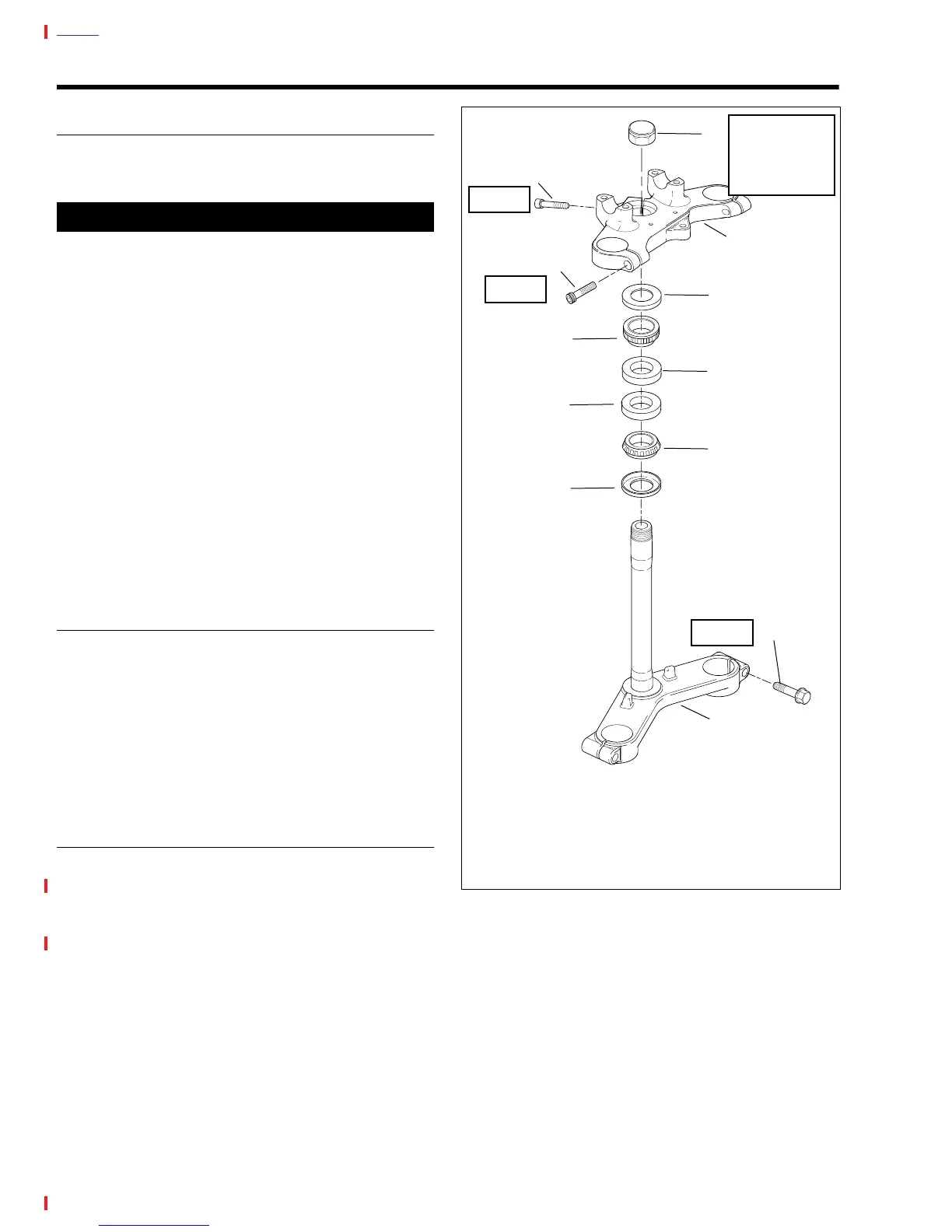
Figure 2-90. Fork Stem and Bracket Assembly
1. Bearing
2. Bearing Cup
3. Dust Shield
4. Cap Nut
5. Upper Triple Clamp
6. Lower Triple Clamp
7. Pinch Screws (2)
8. Pinch Screws (2)
9. Center Cap Pinch
Screw
1
1
3
2
2
3
4
8
9
5
7
6
a0137x2x
7-10 ft-lbs
(10-14 Nm)
To Adjust:
48-52 ft-lbs
(65-71 Nm) then
loosen and re-tighten
to: 28-32 ft-lbs
(38-43 Nm)
13-16 ft-lbs
(18-22 Nm)
22-29 ft-lbs
(30-39 Nm)
Blue Loctite