2002 Buell P3: Maintenance 1-31
HOME
IGNITION TIMING AND IDLE SPEED ADJUSTMENT 1.19
GENERAL
Check ignition timing:
● Every 10,000 mile (16,000 km) service interval.
Check engine idle speed (after bike has warmed up):
● At the 1,000 mile (1,600 km) initial service and every
2,500 mile (4,000 km) service interval thereafter.
DYNAMIC TIMING
NOTE
Use static timing method if inductive timing light is not avail-
able. See 7.8 IGNITION MODULE/ CAM POSITION SEN-
SOR.
Dynamic Timing
1. Remove hex socket timing plug from timing inspection
hole, which is located on right crankcase half and cen-
tered below engine cylinders. Install TIMING MARK
VIEW PLUG (Part No. HD-96295-65D) into timing
inspection hole. Make sure view plug does not touch fly-
wheel.
2. Connect leads of INDUCTIVE TIMING LIGHT (Part No.
HD-33813) to spark plug cable, battery positive (+) termi-
nal, and suitable ground.
3. Make sure vacuum hose is properly installed at carbure-
tor. Start engine.
4. Make sure sidestand is up and transmission is in NEU-
TRAL.
5. Set engine speed to 1200 rpm.
CAUTION
When checking ignition timing, always check at the rpm
listed. Failure to do so may result in running engine with
too much spark advance, and may cause extreme engine
knock and engine failure.
6. See Figure 1-40. Timing light will flash each time an igni-
tion system spark occurs. Aim timing light into timing
inspection hole. The advance timing mark (two dots)
should be centered in timing inspection hole. If this is the
case, ignition timing is properly adjusted. Go to Step 11.
If timing mark is not centered or is not visible in the tim-
ing inspection hole, see to Steps 7-12.
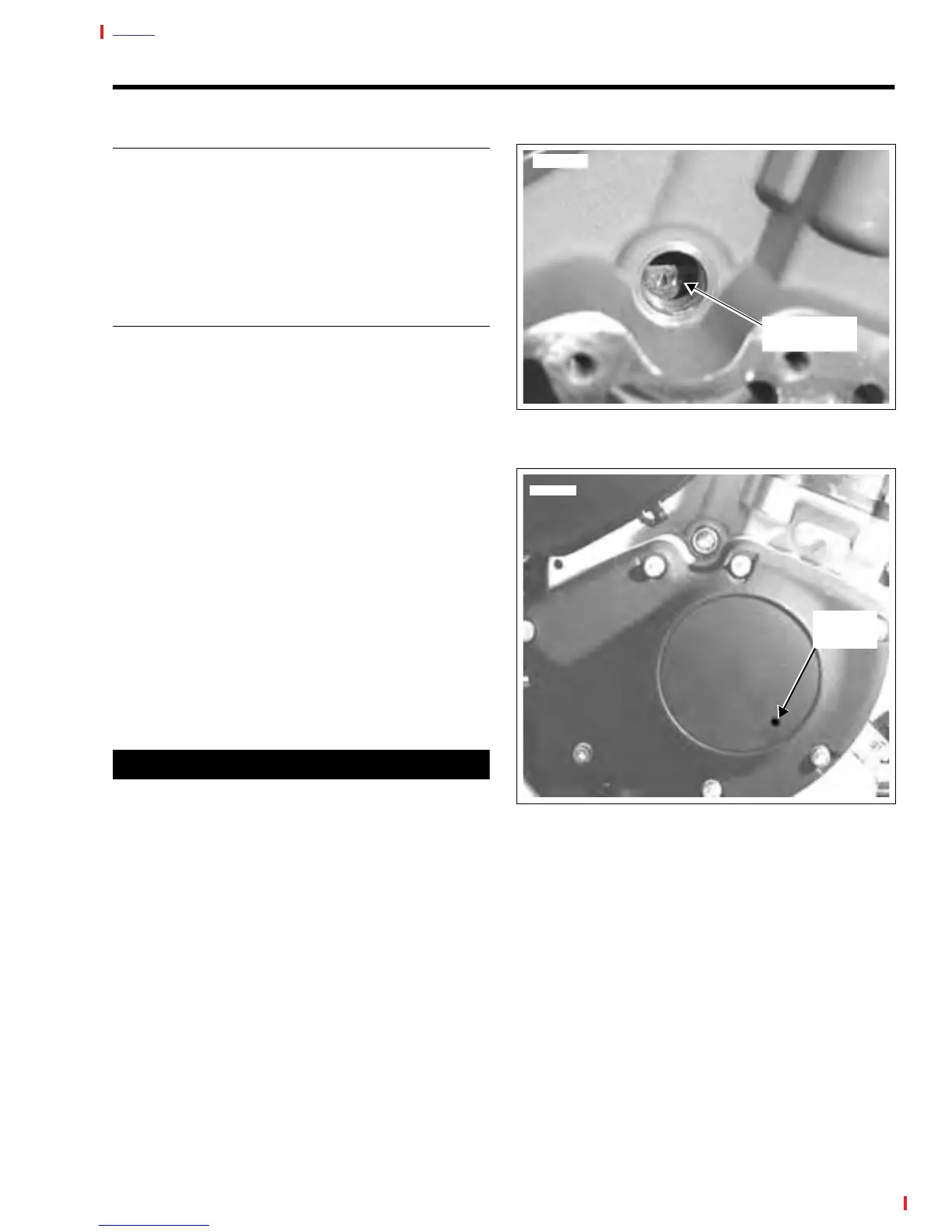
7. See Figure 1-41. Drill hole in location shown and remove
outer timer cover, if not removed.
8. Loosen module plate screws just enough to allow sensor
plate to be rotated using a screwdriver in the plate's
notch.
9. With timing light aimed into inspection hole, rotate mod-
ule plate until advance timing mark is centered in timing
inspection hole (as shown in Figure 7-17).
10. See Figure 1-41. Tighten module plate screws to 15-30
in-lbs (1.7-3.4 Nm)
11. Install new outer cover, if removed.
12. Remove TIMING MARK VIEW PLUG from timing inspec-
tion hole. Install hex socket timing plug. Torque timing
plug to 10-15 ft. lbs (14-21 Nm).
Figure 1-40. Dynamic Ignition Timing
Figure 1-41. Drilling/Removing Timer Cover
7796
Advance
Timing Mark
Drill Hole
Location
7794