7-18 2002 Buell P3: Electrical
HOME
IGNITION MODULE/ CAM POSITION SENSOR 7.8
GENERAL
See Figure 7-17. The ignition module is integrated with the
cam position sensor on the module plate in the gearcase
cover located on the right side of the motorcycle. The inte-
grated ignition module is not repairable. Replace the unit if it
fails.
See 7.2 IGNITION SYSTEM for information on the function
and testing of the integrated ignition module.
See Figure 7-18. The rotor cup is located in the gearcase
cover on the right side of the vehicle behind the integrated
ignition module. The rotor is mounted on the camshaft and
operates at one-half crankshaft speed. See IGNITION TIM-
ING for information on the function, testing and adjustment of
the integrated ignition module and trigger rotor assembly.
REMOVAL
1. Remove seat. See 2.28 SEAT.
11WARNING1WARNING
To protect against shock and accidental start-up of vehi-
cle, disconnect the negative battery cable before proced-
ing. Inadequate safety precautions could result in death
or serious injury.
2. Disconnect negative battery cable from battery terminal.
3. Remove locknut and clamp that secures wire harness
and hoses on right side of motorcycle.
4. See Figure 7-17. Disconnect connector [10] located on
the left side of the frame backbone.
5. Note position of each wiring terminal in plug end of con-
nector.
6. Remove connector terminal pins. See B.2 DEUTSCH
ELECTRICAL CONNECTORS.
11WARNING1WARNING
Always wear proper eye protection when drilling. Flying
debris could result in serious eye injury.
CAUTION
Drilling hole in cover in location other than that specified
may result in module plate damage. Drill carefully only
where indicated to avoid damaging module plate behind
cover.
CAUTION
Do not pry timer cover from bore or damage to gearcase
or ignition module may result.
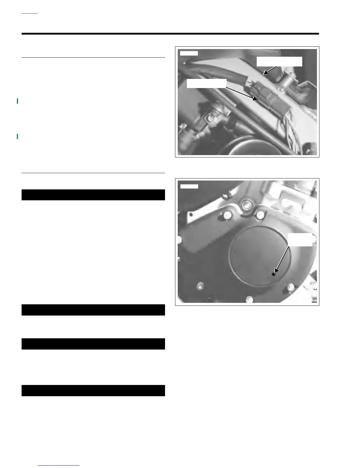
7. See Figure 7-18. Drill hole in outer timer cover at 5:00
position approximately 1/2 inch (13 mm) in from outside
edge. Pull out outer timer cover using 90 degree pick or
other suitable tool.
8. To obtain approximate ignition timing during installation,
scribe alignment marks across module plate and bore in
two places.
9. See Figure 7-19. Remove two module plate mounting
screws. Carefully remove module plate. Remove screw
and rotor cup.
10. Carefully remove camshaft oil seal if damaged or if there
is any evidence of oil leakage past the seal.
Figure 7-17. Integrated Ignition Module Connector [10]
Figure 7-18. Drilling/Removing Timer Cover
7793
Connector [10]
Frame Backbone
Drill Hole
Location
7794