2002 Buell P3: Chassis 2-11
HOME
REAR WHEEL 2.6
REMOVAL
1. Raise rear wheel off floor using REAR WHEEL SUP-
PORT STAND (Part No. B-41174).
2. Inspect wheel bearing end play and service bearings if
necessary. See 2.8 SEALED WHEEL BEARINGS.
NOTE
Do not operate rear brake pedal with rear wheel removed or
caliper piston may be forced out. Reseating piston requires
caliper disassembly.
3. See Figure 2-7. Place rod or screwdriver through axle
hole. Loosen rear axle nut (1) (metric).
4. Remove nut, lockwasher, and flat washer.
5. Pull axle out. Remove right side spacer.
6. Slide carrier with caliper off rotor.
7. Remove left side spacer.
8. Move wheel forward and slide belt off.
DISASSEMBLY
1. See Figure 2-8. Remove and discard five sprocket bolts
(6) from sprocket cover.
2. Remove sprocket cover (7) from sprocket.
3. Remove and discard hardened washers from sprocket.
4. Remove sprocket from rear wheel.
5. Remove five T40 TORX screws and brake rotor from rear
wheel.
CLEANING AND INSPECTION
1. Thoroughly clean all parts in solvent.
2. Inspect all parts for damage or excessive wear.
3. Inspect brake rotor.
a. Measure rotor thickness. Replace if less than 4.5
mm. See 2.14 REAR BRAKE CALIPER.
b. Check rotor surface. Replace if warped or badly
scored.
4. Inspect tire. See 2.9 TIRES.
ASSEMBLY
11WARNING1WARNING
Do not allow brake fluid, bearing grease or other lubri-
cants to contact brake rotor or brake pads or reduced
braking ability may occur which could result in death or
serious injury.
1. Lay wheel on clean work area with rotor side down.
2. Position sprocket on rim with holes in sprocket and rim
aligned.
Use only new P/N BA0511.2Z hardened washers between
sprocket cover and sprocket. Failure to use hardened
washers could cause sprocket to fail. Drive sprocket fail-
ure could lead to loss of control of vehicle which could
result in death or serious injury.
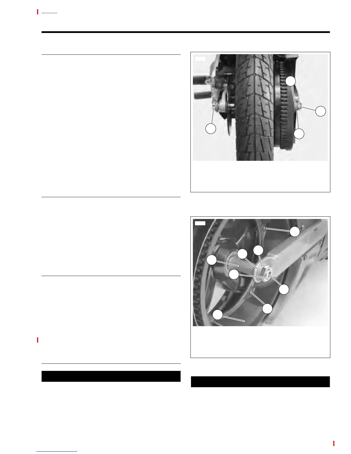
Figure 2-7. Rear Wheel Mounting
Figure 2-8. Rear Axle, Right Side
7747
1. Axle Nut (metric)
2. Lockwasher
3. Washer
4. Axle Hole
1
3
2
4
3
2
1
7701
1. Axle
2. Axle Nut (metric)
3. Lockwasher
4. Washer
5. Spacer
6. Sprocket Bolts (5)
7. Sprocket Cover
4
6
6
7
5