CHAPTER 6 IMAGE FORMATION SYSTEM
6-48
COPYRIGHT
©
1999 CANON INC. CANON GP605/605V REV.0 JAN. 1999 PRINTED IN JAPAN (IMPRIME AU JAPON)
VI . CONTROLLING THE DRUM HEATER
A. Outline
Volume 2>Chapter 4>VI.B. "Drum Heater"
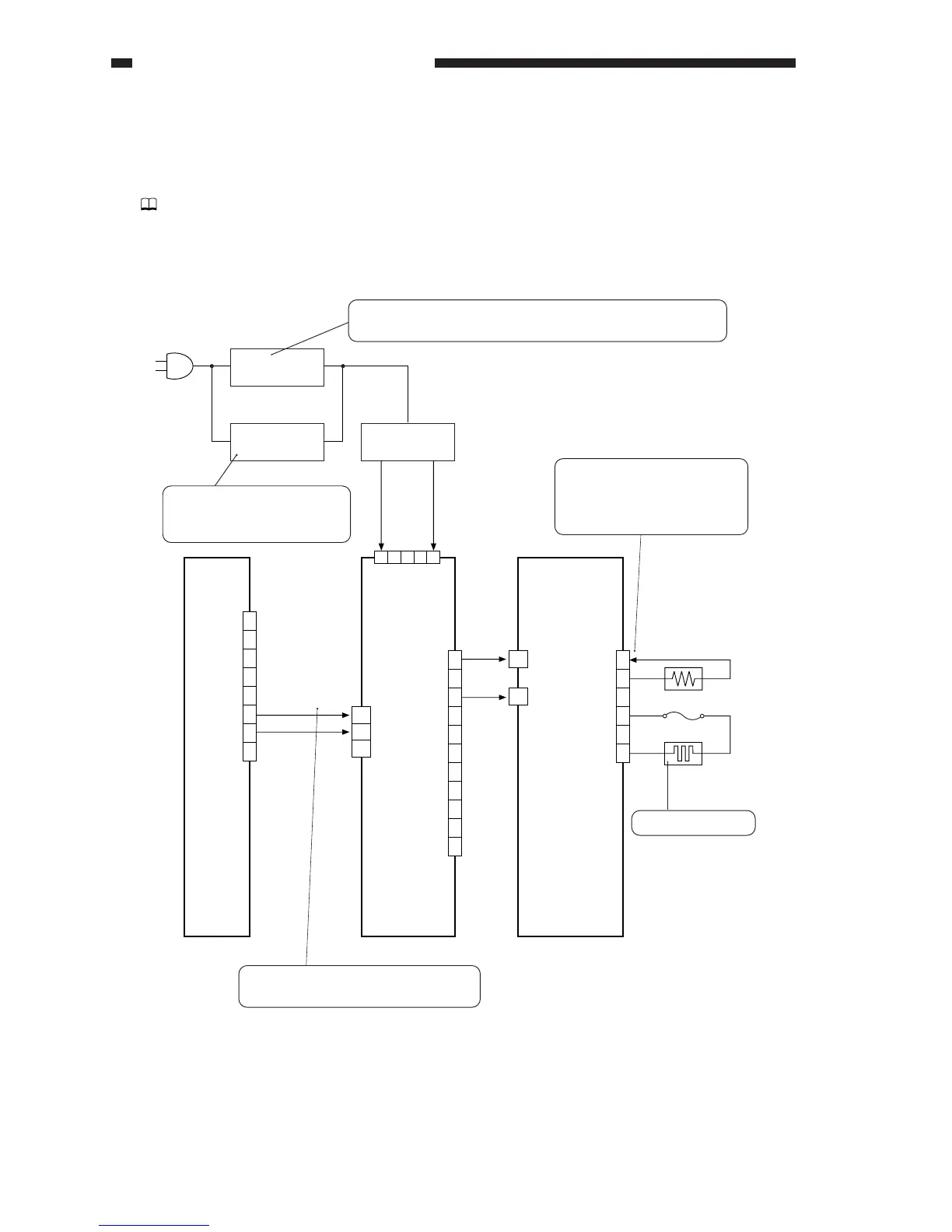
Figure 6-601 shows the construction of the control system for the drum heater.
Figure 6-601 Construction of the Control System
DC controller PCB
1
2
3
4
5
6
J01
W1
3
2
1
W2
1
2
3
4
5
6
7
8
9
10
11
J2602
1
2
3
4
5
6
7
8
J505A
J2605
J2601
SW2
Heater
sw
itch
SW3
1 2 3 4 5
SW1
D-HTR-ON
HT-TEMP
AC (N)
AC (H)
0V
Drum heater (H3)
Thermistor
Fuse
Main power
switch
Front door
switch
AC Input (H)
AC Input (N)
Heater driver PCB
Heater temperature control PCB
When the heater switch is turned on, the heater will remain on
at all times, operating independently of the main power switch.
When the heater switch is off,
the heater operates in sync
with the main power switch.
When the input voltage is
equivalent of 42˚C or more,
the heater will turn off; 42˚C
or less, the heater will turn on.
Controlled to 42˚C
When '1', AC power supply is started to
the heater temperature control PCB.
 Loading...