9-68
COPYRIGHT
©
1999 CANON INC. CANON GP605/605V REV.0 JAN. 1999 PRINTED IN JAPAN (IMPRIME AU JAPON)
CHAPTER 9 EXTERNALS/AUXILIARY MECHANISMS
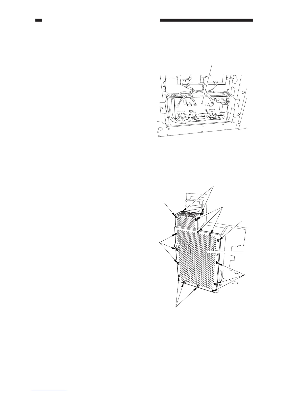
Figure 9-J701
[1]
Figure 9-K701
[1]
[1]
[1]
[1]
[1]
[1]
[1]
[2]
J. Relay PCB
1) Remove the lower left cover.
2) Disconnect the connector from the relay
PCB, and remove the PCB spacer to de-
tach the relay PCB [1].
K. MFC PCB
1) Remove the rear cover.
2) Remove the system box.
3) Remove the 16 screws [1], and detach the
system cover 1 [2].
 Loading...