COPYRIGHT
©
1999 CANON INC. CANON GP605/605V REV.0 JAN. 1999 PRINTED IN JAPAN (IMPRIME AU JAPON)
7-9
CHAPTER 7 PICK-UP/FEEDING SYSTEM
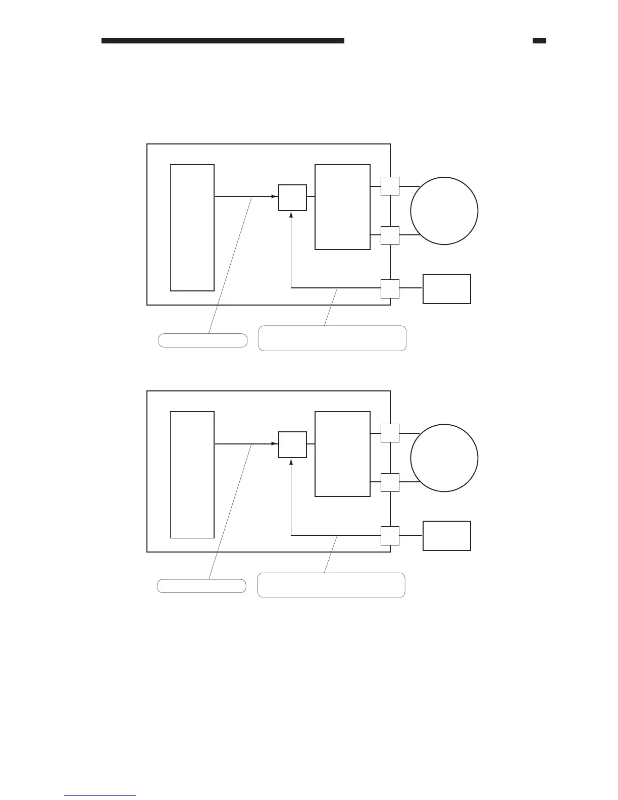
2. Lifter Limiter (deck right/left)
When the lifter moves up and the surface of paper reaches the cassette limit sensor, the drive to
the lifter motor stops.
Figure 7-207 Block Diagram of the Limiter
Q62
M13
Motor
drive
circuit
CPU
Deck right limit
sensor
(PS24)
DC controller PCB
Q53
M14
Motor
drive
circuit
CPU
Deck left limit
sensor
(PS34)
DC controller PCB
B1
B2
A5
J518
J514
A4
A5
B8
J511
J514
Motor drive signal
Motor drive signal
When the lift signal is received,
the motor drive signal is stopped.
When the limit signal is received,
the motor drive signal is stopped.