CHAPTER 8 FIXING SYSTEM
8-24
COPYRIGHT
©
1999 CANON INC. CANON GP605/605V REV.0 JAN. 1999 PRINTED IN JAPAN (IMPRIME AU JAPON)
IV . CONTROLLING THE FIXING ROLLER BIAS
A. Outline
The fixing roller bias is controlled for the following:
[1] Fixing roller bias constant voltage
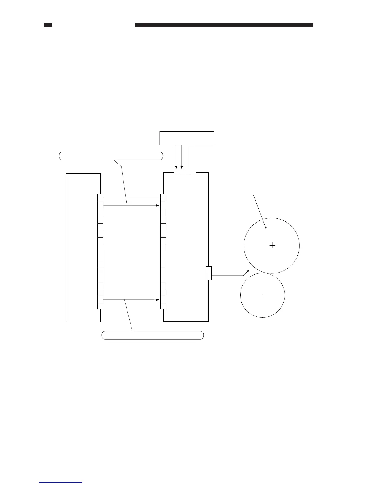
Figure 8-401 shows the construction of the control system used to control the fixing roller bias.
Figure 8-401 Construction of the Control System
DC controller PCB
J510A
DC 600V
J723
1
2
3
4
5
6
7
8
9
10
11
12
13
14
15
16
1
2
3
4
5
6
7
8
9
10
11
12
13
14
15
16
0 V
24 VH
24 VH
HVDC-EN
FGD-ON
High-voltage DC PCB
GND
GND
1
2
3
4
Relay PCB
J733
1
2
When '1', high-voltage output is ready.
When '1', the fixing roller bias turns on.
Fixing roller